
Medication dispensing apparatus with spring-driven locking feature enabled by administration of final dose

a technology of final dose and medication dispensing device, which is applied in the direction of automatic syringes, intravenous devices, syringes, etc., can solve the problems that the platform on which they are based may not allow sufficient options of manufacturers, and the inability to provide insufficient remaining dose indicators may not be practical in all cases, so as to prevent further use, facilitate adaptability, and maximize utilization of space

Active Publication Date: 2009-04-14
ELI LILLY & CO
View PDF70 Cites 59 Cited by
  • Summary
  • Abstract
  • Description
  • Claims
  • Application Information

AI Technical Summary

Benefits of technology

The present invention provides a medication dispensing apparatus with a simple and reliable mechanism to prevent further use after a final dose has been administered. The apparatus can also be adapted by the manufacturer to provide a wide range of mechanical advantages during dose administration, while being designed in a compact and symmetrical manner.

Problems solved by technology

While some users may find such settability undesirable, providing an insufficient remaining dose indicator may not be practical in all cases, such as due to it complicating the pen design.
Still further, a shortcoming with some injector pens is that the design platform on which they are based may not allow a manufacturer sufficient options as to the mechanical advantage to provide, such as a mechanical advantage that can be very small in order to readily inject a large volume dose, or which mechanical advantage can be quite large so as to deliver a small volume dose with a suitable plunger travel.

Method used


Image

  • Medication dispensing apparatus with spring-driven locking feature enabled by administration of final dose
  • Medication dispensing apparatus with spring-driven locking feature enabled by administration of final dose
  • Medication dispensing apparatus with spring-driven locking feature enabled by administration of final dose

Examples


Embodiment Construction

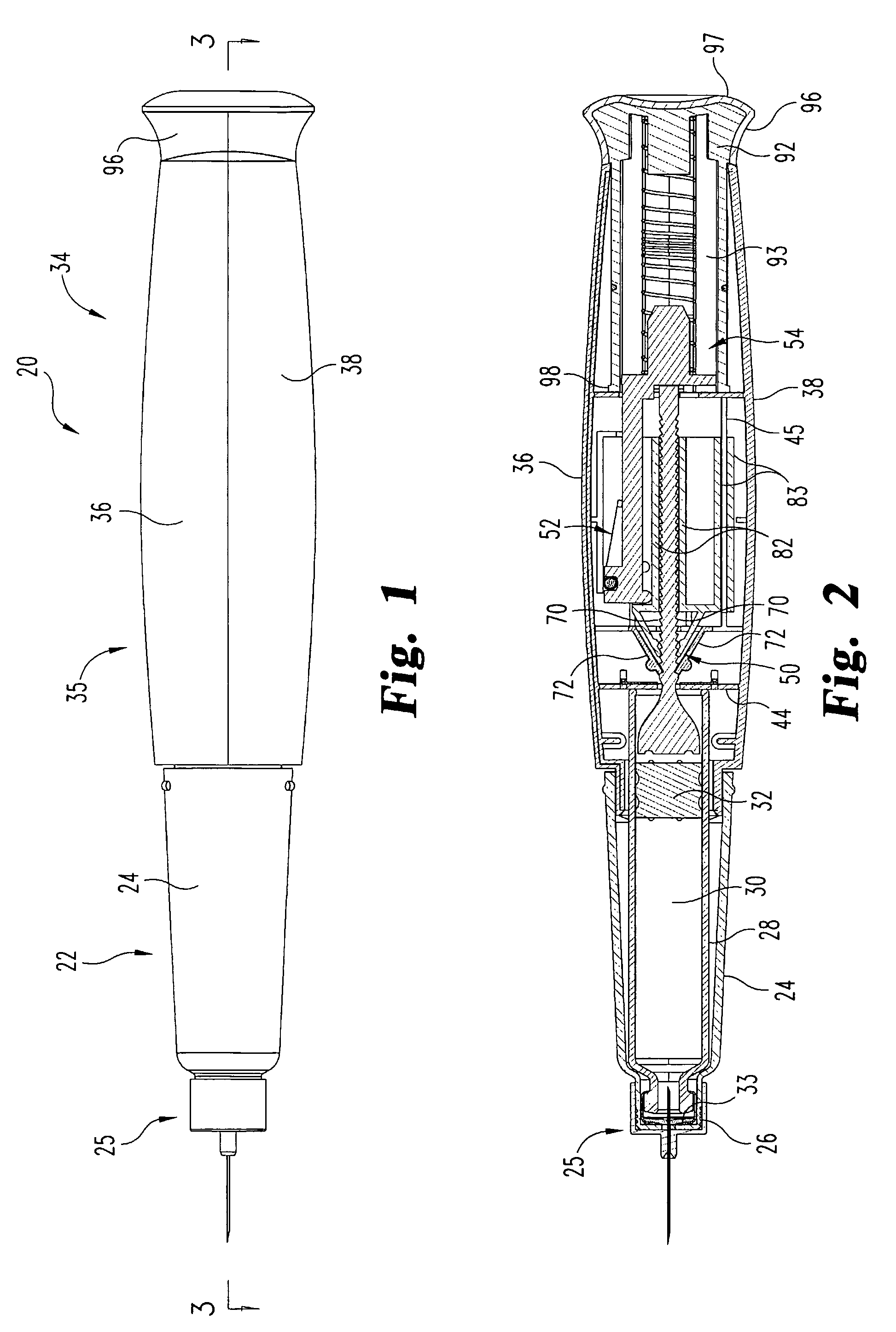
[0025]Referring now to FIGS. 1-12, there is shown a first embodiment of a medication dispensing apparatus of the present invention. Any directional references in this detailed description with respect to FIG. 1 or any of the other Figures, such as front, side or back, or up or down, or top or bottom, are intended for convenience of description, and by itself does not limit the present invention or any of its components to any particular positional or spatial orientation.

[0026]The apparatus, generally designated 20, is an injector pen of a design that builds upon the teachings of U.S. Provisional Patent Application 60 / 557,545, which also was filed with the United States Receiving Office of the World Intellectual Property Organization and assigned application number PCT / US05 / 10205 on even date with the international filing of this application, the entire contents of which are hereby incorporated by reference. Medication injector pen 20 is a disposable pen that is repeatedly operable b...


PUM


Abstract

A medication dispensing apparatus with a spring-driven locking feature includes a drive member movable in a distal direction within a housing, and a fluid container with a piston that is advanceable by the drive member (60) when such drive member is moved distally by a driving means. The apparatus includes a latching element (180) having a skid (190) that is slidable along a surface of the drive member as the drive member passes distally during advancement. The drive member is arranged with the skid so as to maintain a latching lip of the latching element against a spring force in a first position free of the driving means during dose preparing and injecting prior to a final dose administration. The skid-engaging surface shifts distally of the skid such that the skid passes beyond a proximal end of that surface upon administration of a final dose, whereby the latching lip is urged by the spring force from the first position to a second position to physically lock the driving means to prevent further dose preparing and injecting.

Description

CROSS-REFERENCE TO RELATED APPLICATIONS[0001]This Application is a 371 of PCT / US05 / 10206 filed 25 Mar. 2005 which claims benefit to U.S. Provisional Application Ser. No. 60 / 557,545 filed 30 Mar. 2004 and U.S. Provisional Application Ser. No. 60 / 638,027 filed 21 Dec. 2004.BACKGROUND OF THE INVENTION[0002]The present invention pertains to medication dispensing devices, and, in particular, to a portable medication dispensing device such as an injector pen.[0003]Patients suffering from a number of different diseases frequently must inject themselves with medication. To allow a person to conveniently and accurately self-administer medicine, a variety of devices broadly known as injector pens or injection pens have been developed. Generally, these pens are equipped with a cartridge including a piston and containing a multi-dose quantity of liquid medication. A drive member, extending from within a base of the injector pen and operably connected with typically more rearward mechanisms of t...

Claims


Application Information

Patent Timeline
Patent Type & Authority Patents(United States)
IPC IPC(8): A61M5/00A61M5/315A61M5/24A61M5/50
CPCA61M5/31555A61M5/3158A61M5/24A61M5/31511A61M5/31558A61M5/3157A61M5/31571A61M5/502A61M2005/2407A61M5/31541A61M5/20A61M5/315A61M5/50A61M5/152
Inventor JACOBS, ALEXANDER THOMASJUDSON, JARED ALDENROW, GORDON DAVIDSON
Owner ELI LILLY & CO
Learn More