Patient bedding system with dense matrix or individually suspended directly body supporting pins

a patient and bedding technology, applied in the field of patient bedding systems, can solve the problems of difficult maintenance of patient's resting surfaces, difficult transfer of immobilized patients off and onto the bed, and sore affected skin areas, etc., and achieve the effect of convenient transfer

Inactive Publication Date: 2009-04-21
LIBERKOWSKI JANUSZ
View PDF17 Cites 38 Cited by
  • Summary
  • Abstract
  • Description
  • Claims
  • Application Information

AI Technical Summary

Benefits of technology

[0005]The support ends may be of a soft material with a support end diameter such that adjacent support ends snugly contact and such that the weight pressure is reduced to levels similar to a continuous bedding surface. The pins are preferably pressurized by a fluid pressure device for highly balanced contact pressure irrespective the individual pins' load deflection. Balanced contact pressure together with reduced weight pressures result in substantially eliminated pressure peaks on the resting surface.
[0007]A carrying net has a mesh spacing and mesh positions that correspond to the support matrix such that the carrying net may be parked in between the raised support pins. The carrying net may be raised above the support ends of the support pins such that the weight is transferred onto the carrying net. In that way, an immobilized patient may be easily transferred off / onto the bedding device substantially without moving the patient in its resting position.

Problems solved by technology

Particularly, the patient's resting surfaces are difficult to maintain in healthy conditions for long term immobilized patients.
Lack of aeration, body fluid exposure, patient weight peak pressures and other well known issues threaten the effected skin areas to become sore.
The transfer of immobilized patients off and onto the bed is also problematic, especially when the patient may need to be kept immobilized.

Method used


Image

  • Patient bedding system with dense matrix or individually suspended directly body supporting pins
  • Patient bedding system with dense matrix or individually suspended directly body supporting pins
  • Patient bedding system with dense matrix or individually suspended directly body supporting pins

Examples


Embodiment Construction

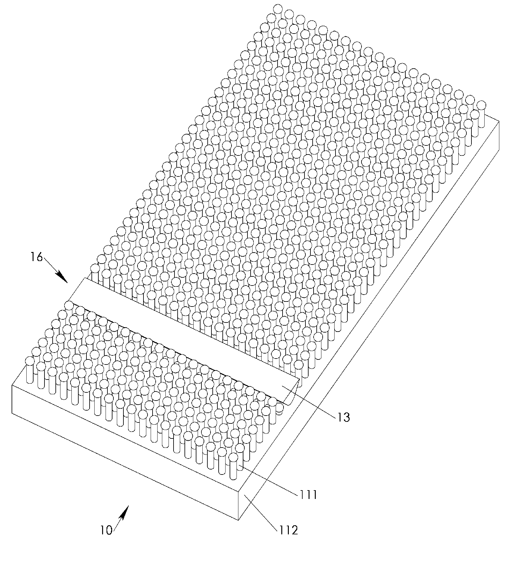
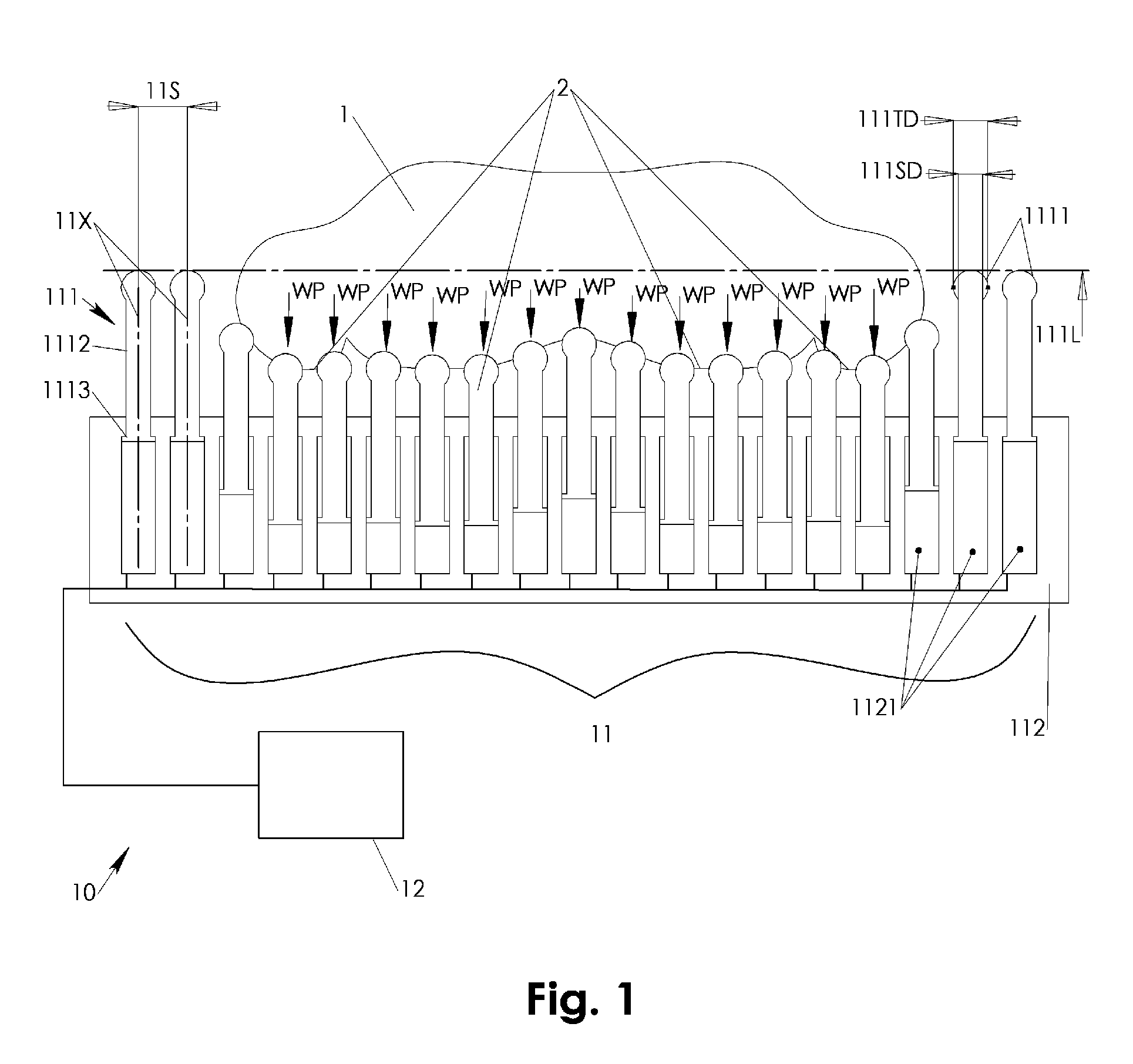
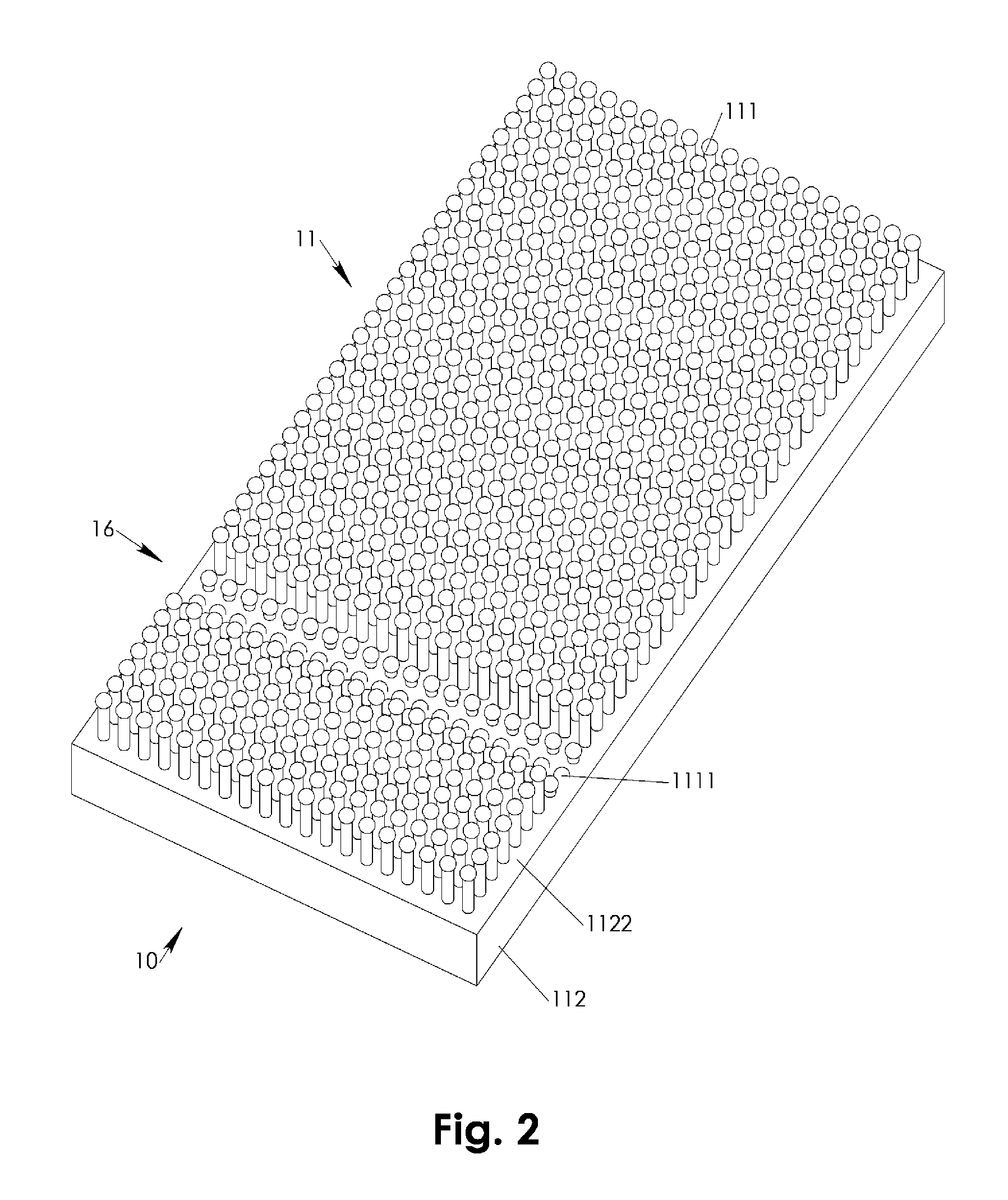
[0014]Referring to FIG. 1, a patient bedding system 10 features a support pin matrix 11 that has a number of directly supporting support pins 111 two dimensionally arrayed and individually springily suspended such that weight pressures WP transmitted via resting surfaces 2 of a bedded patient 1 are directly and substantially evenly opposed irrespective of the resting surfaces' 2 curvature and configuration. Configuration and curvature of the resting surface 2 may vary along the patient's 1 body as may be well appreciated by anyone skilled in the art.

[0015]At least one but preferably each of the support pins 111 has a support end 1111 and a pin shaft 1112. The support ends 1111 are optionally of a soft material that has a softness of up to that of body tissue such that weight pressure WP causes the support end 1111 to resiliently deform and snugly contact the respective resting surface 2 area. The pin shaft 1112 is of a stiff material such that it may be linearly guided within guidin...


PUM


Abstract

A support pin matrix features a number of support pins densely two dimensionally arrayed and individually springily suspended such that a patient's body or body portions may be bedded directly on the support pins. The pins are preferably pressurized by a fluid pressure system for highly balanced contact pressure irrespective the individual pins' load deflection. A control system may provide a pin retraction wave of the support pins. A body resting surface accessing device may be moved across the support pin matrix and beneath a bedded patient in conjunction with the pin retraction wave. The resting surface accessing device may be configured for cleaning, drying, inspecting, irradiating, and / or massaging the body resting surface and / or for maintaining the body support pin matrix. A body carrying net may be retracted and raised in between the body support pins to lift the patient off the support pin matrix.

Description

FIELD OF INVENTION[0001]The present invention relates to bedding devices and systems for patients. In particular, the present invention relates to bedding devices and systems utilizing a matrix of individually suspended support pins.BACKGROUND OF INVENTION[0002]Bedding of immobilized patients is a challenging issue as is well known in the art. Particularly, the patient's resting surfaces are difficult to maintain in healthy conditions for long term immobilized patients. Lack of aeration, body fluid exposure, patient weight peak pressures and other well known issues threaten the effected skin areas to become sore. Therefore, there exists a need for a bedding device and system for long term bedding of immobilized patients that provides aeration, separation from body fluids and a balanced support of body weight avoiding patient weight peak pressures. The present invention addresses this need.[0003]The transfer of immobilized patients off and onto the bed is also problematic, especially...

Claims


Application Information

Patent Timeline
Patent Type & Authority Patents(United States)
IPC IPC(8): A47C17/00
CPCA47C23/002A61G7/05707A61H7/001A61H2203/0456
Inventor LIBERKOWSKI, JANUSZ
Owner LIBERKOWSKI JANUSZ
Why Eureka
Try Eureka