Liquid crystal display having improved retardation film

Inactive Publication Date: 2009-04-21
SAMSUNG DISPLAY CO LTD
View PDF10 Cites 5 Cited by
  • Summary
  • Abstract
  • Description
  • Claims
  • Application Information

AI Technical Summary

Benefits of technology

[0022]It is therefore one feature of the invention to provide a liquid crystal display having an impro

Problems solved by technology

However, the reflection type liquid crystal displays of the early stage hardly meet the requirement for high quality, multi-media display in the respects of correspondence time, color appearance, efficiency of reflection, and contrast ratio.
However, they have other types of problems such as high operation voltage and difficulties in gray scale display.
But, in the present Window environment, normally dark MTN mode causes increase in power consumption and l

Method used


Image

  • Liquid crystal display having improved retardation film
  • Liquid crystal display having improved retardation film
  • Liquid crystal display having improved retardation film

Examples


Example

Embodiment 1

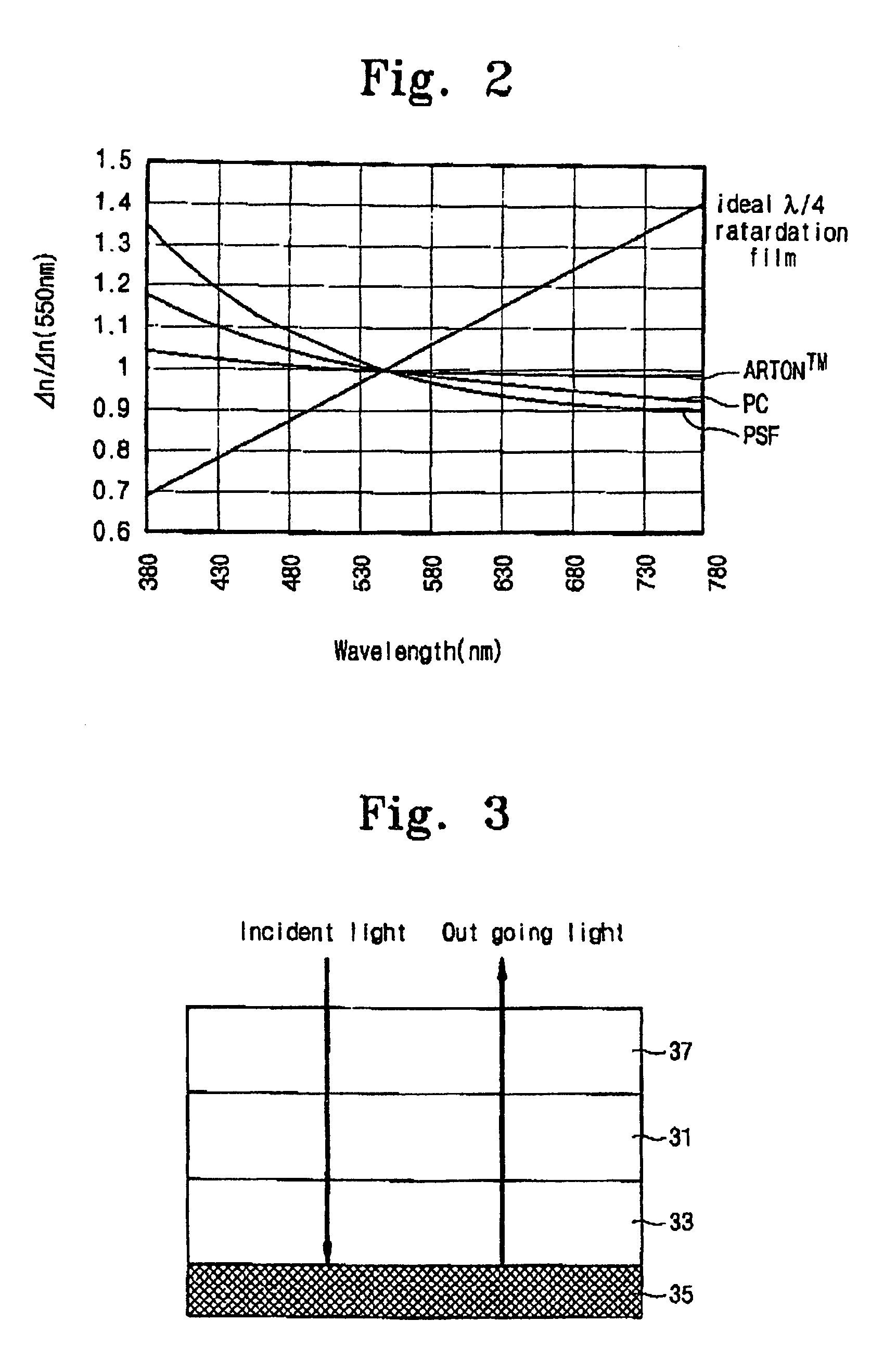
[0048]FIG. 3 shows a characteristic structure of an optical apparatus designed for obtaining result of the invention and deciding the proper angle, and FIG. 4 is a descriptive view showing relationship of an axis of an element layer composing the apparatus shown in FIG. 3.

[0049]In the apparatus, a polarizer 37, a half lambda retardation film 31, a quarter lambda retardation film 33 and reflector 35 are sequentially attached without a space. For an experiment, the retardation films rotate gradually clockwise by relation equation Θ2=2×Θ1±145°. Intensity to the reflected light is measured. At the proper angles, 1 and Θ2, the intensity of the reflected light has a minimum value.

[0050]With regard to the proceeding of light in the optical apparatus, proper angles are Θ1 and Θ2. The incident light is polarized and, circularly polarized and reflected. In the reflection, clockwise circularly polarized light is transformed to counterclockwise circularly polarized light. The circul...

Example

Embodiment 2

[0069]Embodiment 2 is related to a reflective-transmissive type liquid crystal display.

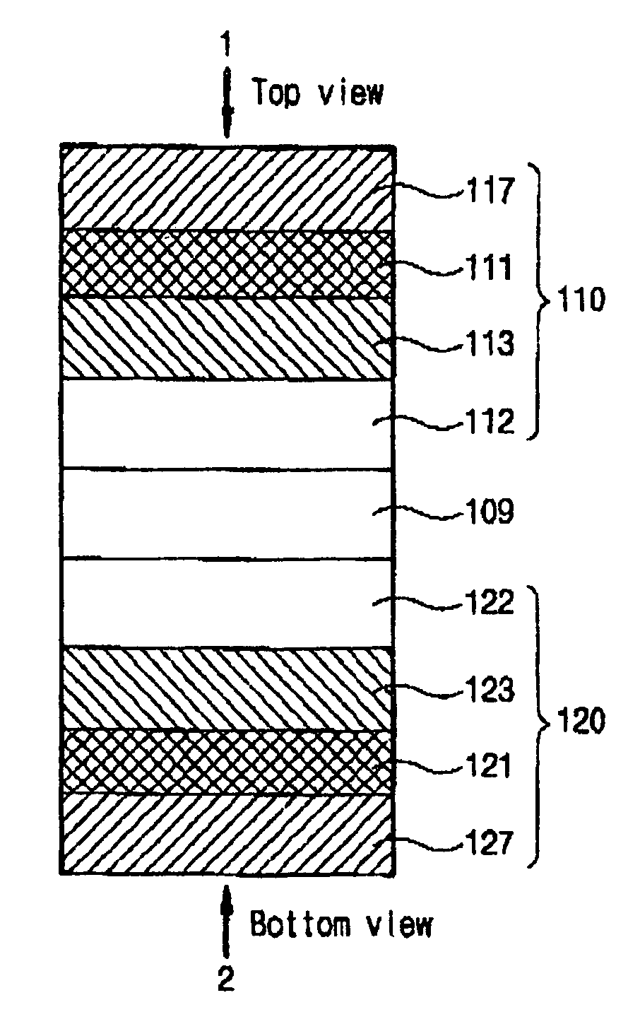
[0070]A part of a pixel is a transmissive region and the other is a reflective region. FIG. 11, showing an example of a reflective-transmissive type liquid crystal display panel or a transmissive type liquid crystal display panel, is a cross-sectional view of the transmissive region. FIG. 12 and FIG. 13 are plane views from a top and from a bottom of FIG. 11, respectively. The axis arrangement of polarizers and retardation films adopts combination 2 in the following “TABLE 3”.

[0071]Polarizers 117 and 127 attached in an upper and a lower panel glasses 112 and 122 are arranged, so that two transmissive axes are at a right angle each other. A liquid crystal layer 109 is placed between the upper and the lower panel glasses 112 and 122.

[0072]With regard to the upper panel plate 110, a quarter lambda retardation film 113, a half lambda retardation film 111, and a polarizer 117 are sequential...


PUM


Abstract

A liquid crystal display having improved retardation plate is described. In the liquid crystal display, at least one of two panel plates has a polarizer placed on an outer side which is opposite to a liquid crystal layer and a quarter wavelength retardation plate between a substrate glass and the polarizer. The quarter wavelength retardation plate is composed of two retardation films including a half wavelength and a quarter wavelength retardation film. A slow axis of a half λ film which is adjacent to the polarizer makes an angle of Θ1 with a transmissive axis of the polarizer and that of a quarter λ film which is adjacent to the substrate glass makes an angle of Θ2 where Θ2=2×Θ1±45 degree. The retardation films are single-axial films. The specific angle Θ1 is one of degree values (15, 75, 105, and 165). In a transmissive type liquid crystal display, a structure of the other panel plate is similar to that of one panel plate and combination to the values (Θ1, Θ2, Θ3, Θ4) is one selected from the group consisting of combinations (15, 75, 165, 105), (75,15,105,165), (105,165,75,15), and (165,105,15,75).

Description

FIELD OF THE INVENTION[0001]The present invention is related to liquid crystal displays and, more particularly, liquid crystal displays having retardation film arrangement which can exactly be operated in a wide range of visible light.BACKGROUND OF THE INVENTION[0002]In a display market, a liquid crystal display rapidly has enlarged its territory and replaced CRT because it has some merits (better properties) such as low power consumption, small size especially in thickness, and lightness.[0003]Referring to the early stage products of a liquid crystal display, a reflection type was the most common type. So the external light source to light the display panel was required. However, the reflection type liquid crystal displays of the early stage hardly meet the requirement for high quality, multi-media display in the respects of correspondence time, color appearance, efficiency of reflection, and contrast ratio.[0004]Research and development on the other types of liquid crystal display...

Claims


Application Information

Patent Timeline
IPC IPC(8): G02F1/1335G02B5/30G02F1/13363G02F1/137G02F1/139
CPCG02F1/13363G02F2001/133637G02F2001/133638G02F1/133637G02F1/133638G02F1/1335
Inventor JANG, YONG-KYU
Owner SAMSUNG DISPLAY CO LTD
Why Eureka
Try Eureka