Fuel injection control system

a technology of control system and fuel injection, which is applied in the direction of electrical control, process and machine control, etc., can solve the problems of deterioration of the exhaust characteristic of the internal combustion engine, the difficulty of obtaining a learned value for each of the fuel injectors, and the drivability of the vehicl

Active Publication Date: 2009-04-21
DENSO CORP
View PDF8 Cites 18 Cited by
  • Summary
  • Abstract
  • Description
  • Claims
  • Application Information

AI Technical Summary

Benefits of technology

[0033]In view of the background, an object of at least one aspect of the present invention is to provide fuel injection control systems, which are capable of properly learning the amount of deviation from a reference injection characteristic of a fuel injector; the reference injection characteristic being designed when a full movement stroke of a valve is kept unchanged.

Problems solved by technology

Even if the fuel-quantity parameters for a plurality of fuel injectors of an internal combustion engine are determined to be equalized to each other, however, individual injection characteristics of the fuel injectors different therebetween may cause variations in actually sprayed fuel quantities therefrom.
This may make it difficult to obtain a learned value for each of the fuel injectors for compensating the variations in its fuel injection characteristics under high speed and high-load conditions of the internal combustion engine.
Specifically, the variations in the fuel injection characteristics of each of the fuel injectors under high speed and high-load conditions of the internal combustion engine may cause deterioration of the exhaust characteristic of the internal combustion engine and / or the drivability of a vehicle in which the internal combustion engine is installed.

Method used


Image

  • Fuel injection control system
  • Fuel injection control system
  • Fuel injection control system

Examples


first embodiment

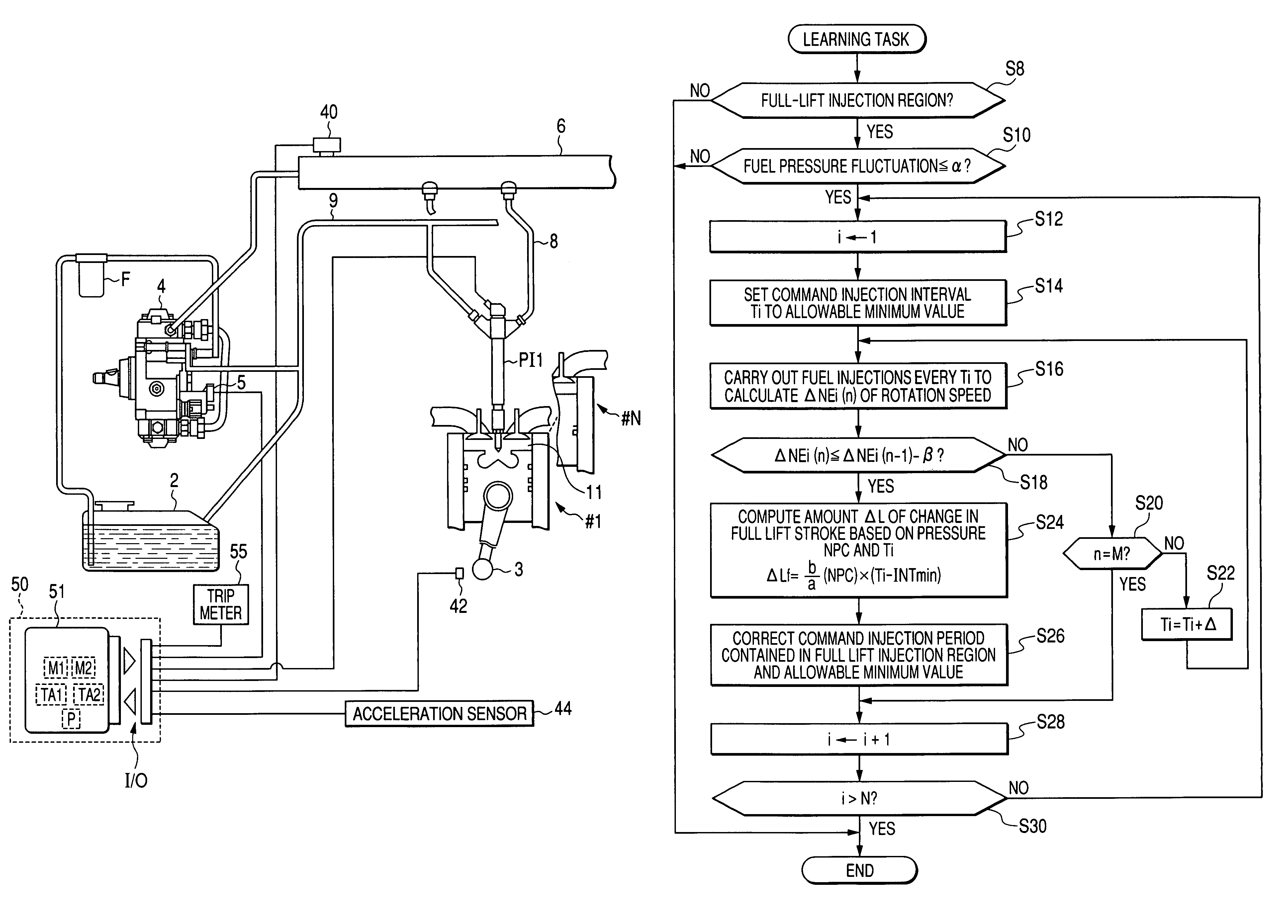
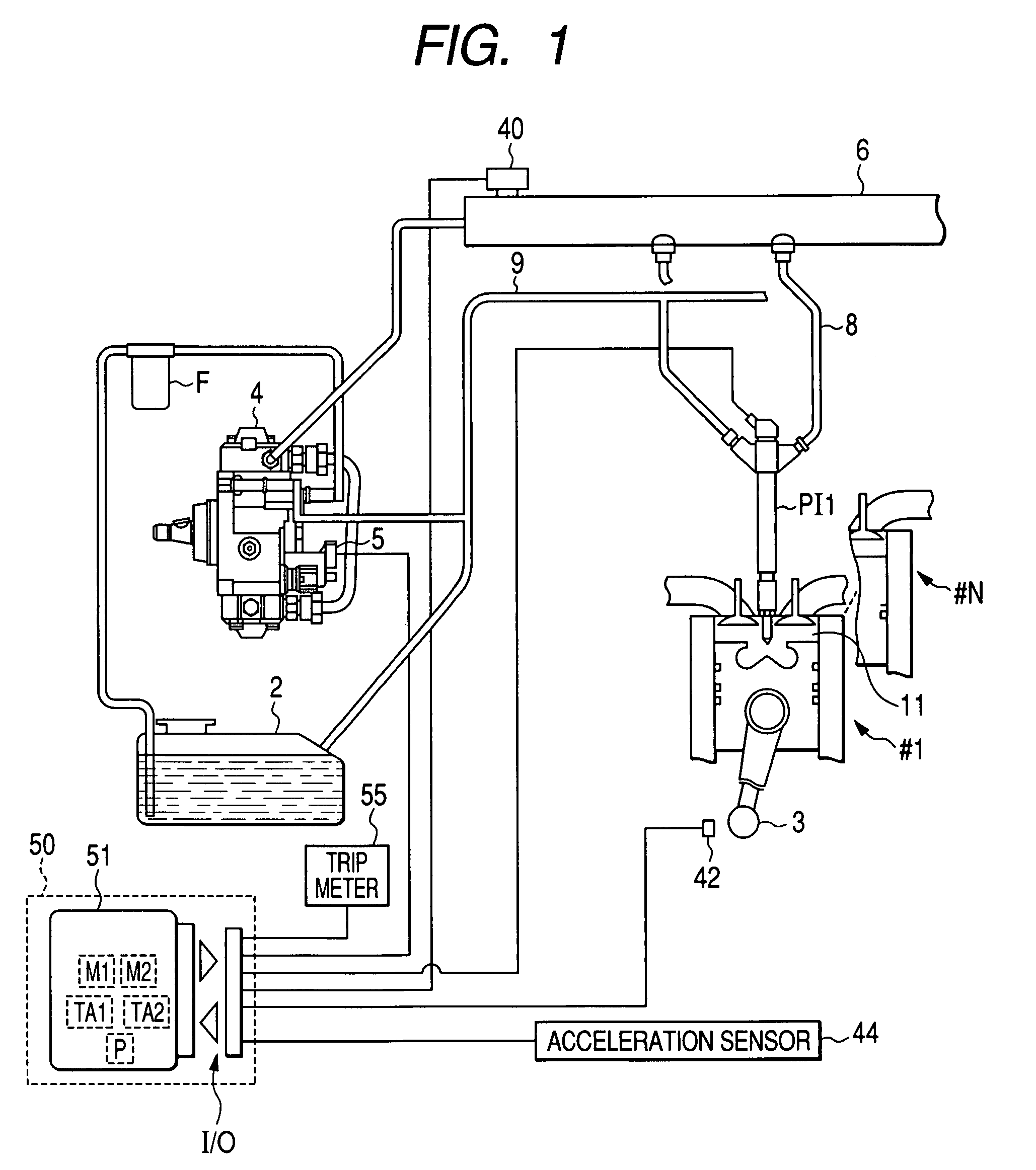
[0056]Referring to FIG. 1, there is illustrated the overall structure of a fuel injection control system according to a first embodiment, which is applied for control of a direct fuel-injection engine, such as a diesel engine 1, installed in a vehicle.

[0057]The diesel engine 1 is composed of N cylinders #1 to #N as an example; this N is a positive integer greater than 1, such as 4. Identifier numbers “1” to “N” are assigned to the cylinders #1 to #N, respectively.

[0058]As illustrated in FIG. 1, the system is provided with a fuel tank 2 of the diesel engine 1 accommodating fuel, which is pumped up by a fuel pump 4 driven by rotation of a crankshaft 3 of the diesel engine 1. During the pumping-up process by the fuel pump 4, the fuel is pressurized and supplied to a common rail 6 via a filter F while it is metered by a metering valve 5 based on a control signal sent from an ECU described hereinafter.

[0059]The common rail 6 serves as an accumulator shared by the cylinders #1 to #N and o...

second embodiment

[0231]A fuel injection control system according to a second embodiment of the present invention will be described hereinafter with emphasis on the difference points from the structure and operations of the fuel injection control system according to the first embodiment.

[0232]The diesel engine according to the second embodiment includes a plurality of piezo injectors PI1A to PINA for the respective cylinders #1 to #N.

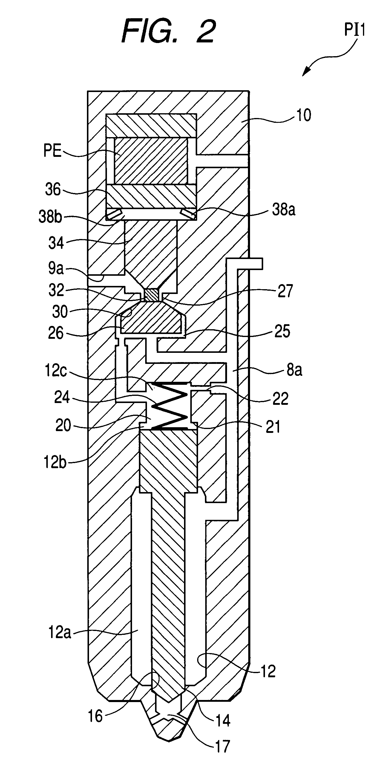
[0233]FIG. 9 schematically illustrates an example of the structure of a piezo injector PI1A. Note that the other piezo injectors PI2A to PINA have the same structure of the piezo injector PI1A.

[0234]The piezo injector PI1A consists of a substantially cylindrical body (housing) 60. The body 60 is formed at its one end (one distal end) with a nozzle 61 at the center thereof. The body 60 is formed at the other end side with a pair of port into which the high-pressure fuel passage 8 and the low-pressure fuel passage 9 are coupled to be communicated.

[0235]The body 60 is also ...

third embodiment

[0325]A fuel injection control system according to a third embodiment of the present invention will be described hereinafter with emphasis on the difference points from the structure and operations of the fuel injection control system according to the first or second embodiment.

[0326]FIG. 13 schematically illustrates processes to be executable by the microcomputer 51A in accordance with at least one program stored in the storage unit for executing the minimum interval detecting task and the learning task according to the third embodiment. Note that like reference characters are assigned to like steps in FIGS. 7 and 13, and therefore, descriptions of the like steps will be therefore omitted. Like the first embodiment, the sequence of the processes is repeatedly executed by the microcomputer 51A every cycle of, for example, 5,000 km of driving.

[0327]Specifically, the processes in steps S8 to S14 illustrated in FIG. 13, which are substantially identical to those in corresponding steps ...


PUM


Abstract

An apparatus aims at learning a deviation from a reference injection characteristic of a fuel injector provided for a cylinder of an engine having an output shaft. In the apparatus, a detecting unit is configured to detect a minimum interval between temporally adjacent fuel injection periods in the plurality of fuel injection periods based on a behavior of the output shaft during execution of the plurality of fuel injections. The minimum interval maintains the temporally adjacent fuel injection periods to be non-overlapped with each other. A learning unit is configured to learn the deviation from the reference injection characteristic of the fuel injector based on the detected minimum interval.

Description

CROSS REFERENCE TO RELATED APPLICATION[0001]This application is based on Japanese Patent Application 2006-199452 filed on Jul. 21, 2006. This application aims at the benefit of priority from the Japanese Patent Application, so that the descriptions of which are all incorporated herein by reference.BACKGROUND OF THE INVENTION[0002]1. Field of the Invention[0003]The present invention relates to fuel injection control systems used for internal combustion engines; these systems are capable of learning at least one parameter indicative of a change in the injection characteristics of a fuel injector.[0004]2. Description of the Related Art[0005]Fuel injection control systems are commonly used to control fuel injection by an injector for each cylinder of an engine.[0006]When a needle valve is rested (seated) upon an inner wall (valve seat) of a fuel injector, the fuel injector is closed. When the needle valve is moved from the valve seat so that a physical distance between the needle valve ...

Claims


Application Information

Patent Timeline
Patent Type & Authority Patents(United States)
IPC IPC(8): G06F19/00F02M51/00F02D41/38F02D41/40F02D45/00F02M45/02F02M47/00F02M65/00
CPCF02D41/1497F02D41/2438F02D41/2467F02D41/402F02M47/027F02D41/2096F02D41/247F02D41/3836F02D2200/0602Y02T10/44Y02T10/40
Inventor FUJII, HIROTO
Owner DENSO CORP
Why Eureka
Try Eureka