Learning of EGR valve lift and EGR valve flow transfer function

a technology of egr valve and flow transfer function, which is applied in the direction of machines/engines, electric control, combustion air/fuel air treatment, etc., can solve the problems of reducing engine performance, increasing emission, and reducing fuel economy, so as to reduce regulated emissions, improve fuel economy, and reduce combustion temperatures

Active Publication Date: 2016-02-23
FORD GLOBAL TECH LLC
View PDF18 Cites 14 Cited by
  • Summary
  • Abstract
  • Description
  • Claims
  • Application Information

AI Technical Summary

Benefits of technology

[0002]Engine systems may be equipped with exhaust gas recirculation systems that recirculate a portion of exhaust gas from an engine exhaust to an engine intake system to improve fuel economy and reduce regulated emissions. The recirculated exhaust gas may dilute the oxygen concentration of the intake air resulting in reduced combustion temperatures, and consequently, formation of nitrogen oxides in the exhaust may be reduced. In order to achieve improved engine operation and reduced emissions, a targeted EGR flow rate and air / fuel ratio may be maintained by adjusting engine actuators.
[0009]In this way, methods for an engine control system may be provided to accurately learn the changes in EGR valve lift and adjust the flow rate based on the valve lift. By learning the effective leaking area of the EGR valve during valve-closed conditions, and / or by learning the differential pressure transfer function during different valve lift conditions, adjustments to the effective EGR valve area may be performed. As a result, more accurate EGR flow measurements may be obtained and consequently, improved fuel economy, improved engine performance and reduced emissions may be obtained. Further, a change in EGR flow from a nominal flow may be calculated by utilizing the learned leak area and transfer function. Upon determining that the change in EGR flow is greater than a threshold change, EGR valve degradation may be indicated. By determining EGR valve degradation based on the learned leak area and / or transfer function, more accurate leak diagnostics may be obtained and more accurate control of EGR may be achieved.

Problems solved by technology

Errors in EGR flow measurement may lead to reduced fuel economy, decreased engine performance and increased emission.
However, the inventors herein have identified issues with such systems.
Non-uniform soot build-up may lead to changes in effective valve area, which may result in EGR measurement errors.
Consequently, delays and insufficiencies in EGR flow may occur, which in turn may result in degraded fuel economy, engine performance and emission.

Method used


Image

  • Learning of EGR valve lift and EGR valve flow transfer function
  • Learning of EGR valve lift and EGR valve flow transfer function
  • Learning of EGR valve lift and EGR valve flow transfer function

Examples


Embodiment Construction

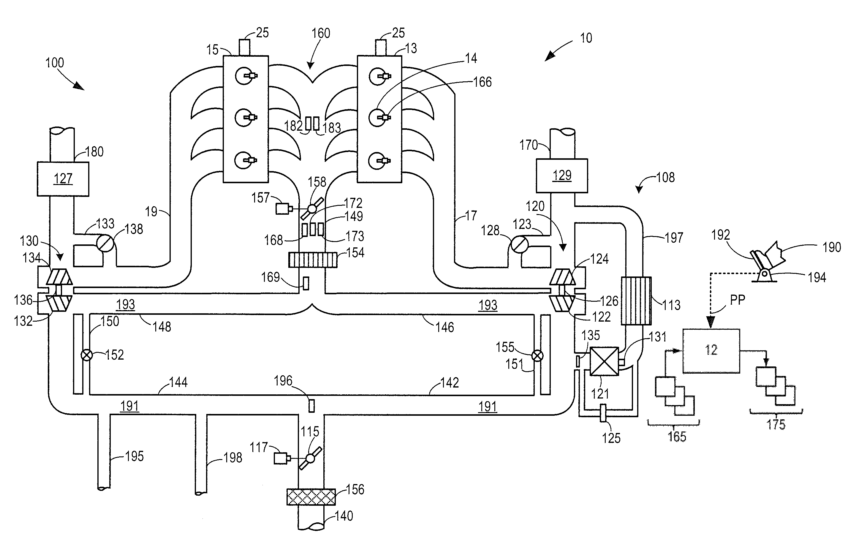
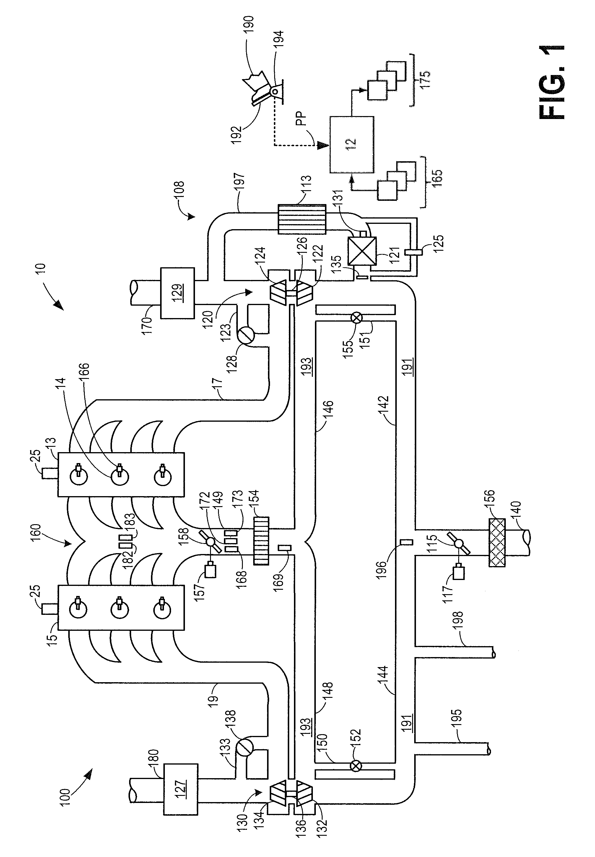
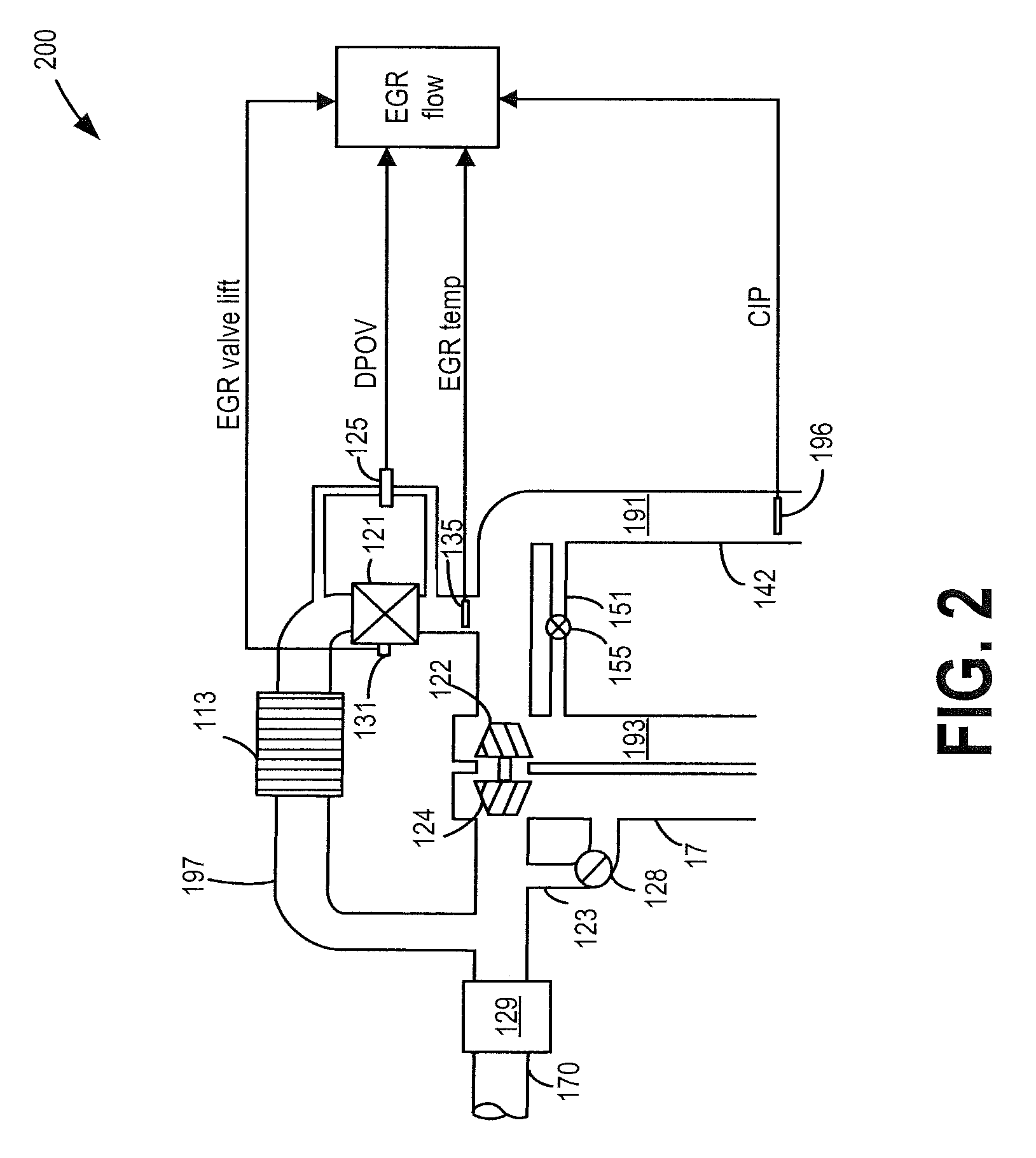
[0022]Methods and systems are provided for increasing the accuracy of EGR flow measurement determined based on a delta pressure over valve (DPOV) measurement system in an engine system (such as engine system of FIG. 1) by learning errors in EGR flow. Based on signals from an EGR system, as shown at FIG. 2, a DPOV measurement method may be implemented to determine EGR flow. Soot build-up may cause errors in EGR valve lift leading to errors in EGR flow measurement by DPOV. A controller may perform a routine such as the routine at FIG. 3C to determine EGR valve leakage rate during closed EGR valve conditions. The EGR leakage rate thus obtained may be utilized for EGR valve diagnostics as described at FIG. 3A, and to correct an effective EGR flow area for EGR flow measurements as described at FIG. 3B. Further, the controller may perform a routine such as the routine at FIG. 4C to determine DPOV transfer function that may allow learning of changes in EGR valve flow characteristics at dif...


PUM


Abstract

Methods and systems are provided for improving accuracy of delta pressure over valve (DPOV) based EGR flow measurement during low valve lift conditions by learning errors in EGR valve lift and / or EGR valve flow transfer function.

Description

TECHNICAL FIELD[0001]The present application relates to systems and methods for adjusting operation based on exhaust gas recirculation (EGR) valve leakage.BACKGROUND AND SUMMARY[0002]Engine systems may be equipped with exhaust gas recirculation systems that recirculate a portion of exhaust gas from an engine exhaust to an engine intake system to improve fuel economy and reduce regulated emissions. The recirculated exhaust gas may dilute the oxygen concentration of the intake air resulting in reduced combustion temperatures, and consequently, formation of nitrogen oxides in the exhaust may be reduced. In order to achieve improved engine operation and reduced emissions, a targeted EGR flow rate and air / fuel ratio may be maintained by adjusting engine actuators.[0003]An EGR valve may be included in an exhaust gas recirculation path to control an amount of exhaust gas recirculated to achieve a desired air intake dilution. Turbocharged engine systems may include a low-pressure EGR (LP EG...

Claims


Application Information

Patent Timeline
Patent Type & Authority Patents(United States)
IPC IPC(8): F02D41/26F02D41/00F02D41/24F02M35/10F02D11/10F02D41/14
CPCF02D41/0077F02D41/0072F02D41/2464F02M26/07F02M26/47F02M26/49F02M26/48F02M35/10393F02D41/1448F02D41/1456F02D2011/102F02D2041/0017F02M26/43F02M26/08F02M26/23Y02T10/40
Inventor SURNILLA, GOPICHANDRASTYLES, DANIEL JOSEPHHILDITCH, JAMES ALFREDALI, IMTIAZ
Owner FORD GLOBAL TECH LLC
Why Eureka
Try Eureka