Mode-setting device for photographing device

a technology of mode-setting device and photographing device, which is applied in the field of mode-setting device for photographing device, can solve the problems of low operational convenience, unnecessary consumption of electric power, and unnecessary time-consuming operations, and achieve the effect of preventing unnecessary operations and high operational convenien

Inactive Publication Date: 2009-04-28
RICOH IMAGING COMPANY
View PDF10 Cites 5 Cited by
  • Summary
  • Abstract
  • Description
  • Claims
  • Application Information

AI Technical Summary

Benefits of technology

[0009]Therefore, an objective of the present invention is to provide a mode-setting device, such as a mode dial mechanism, for a photographing device that can prevent unnecessary operations and that has high operational convenience.

Problems solved by technology

Due to these unnecessary movements of the photographing lens, electric power is unnecessarily consumed, and the operations take unnecessary time.
However, for such a mode dial, the operational convenience is low, and the time required for operations is longer than for an endless mode dial, because rotating operations can be interrupted when the mode dial is in the end position.
Further, when a mode where a photographing lens is housed is selected without a mode dial, the selection operation becomes complicated, and the structure of the photographing device can be complex.

Method used


Image

  • Mode-setting device for photographing device
  • Mode-setting device for photographing device
  • Mode-setting device for photographing device

Examples


Embodiment Construction

[0022]Hereinafter, the preferred embodiment of the present invention is described with reference to the attached drawings.

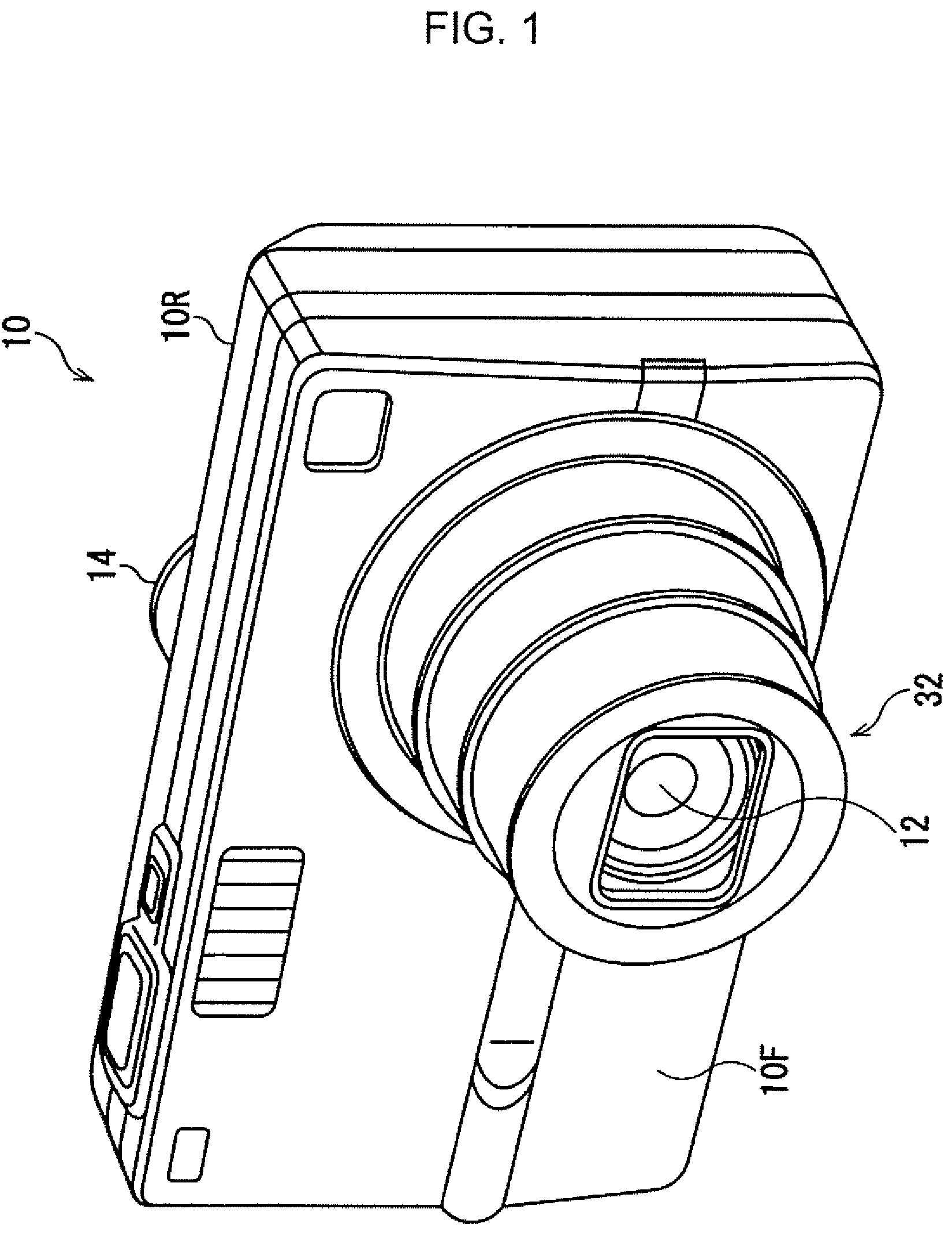
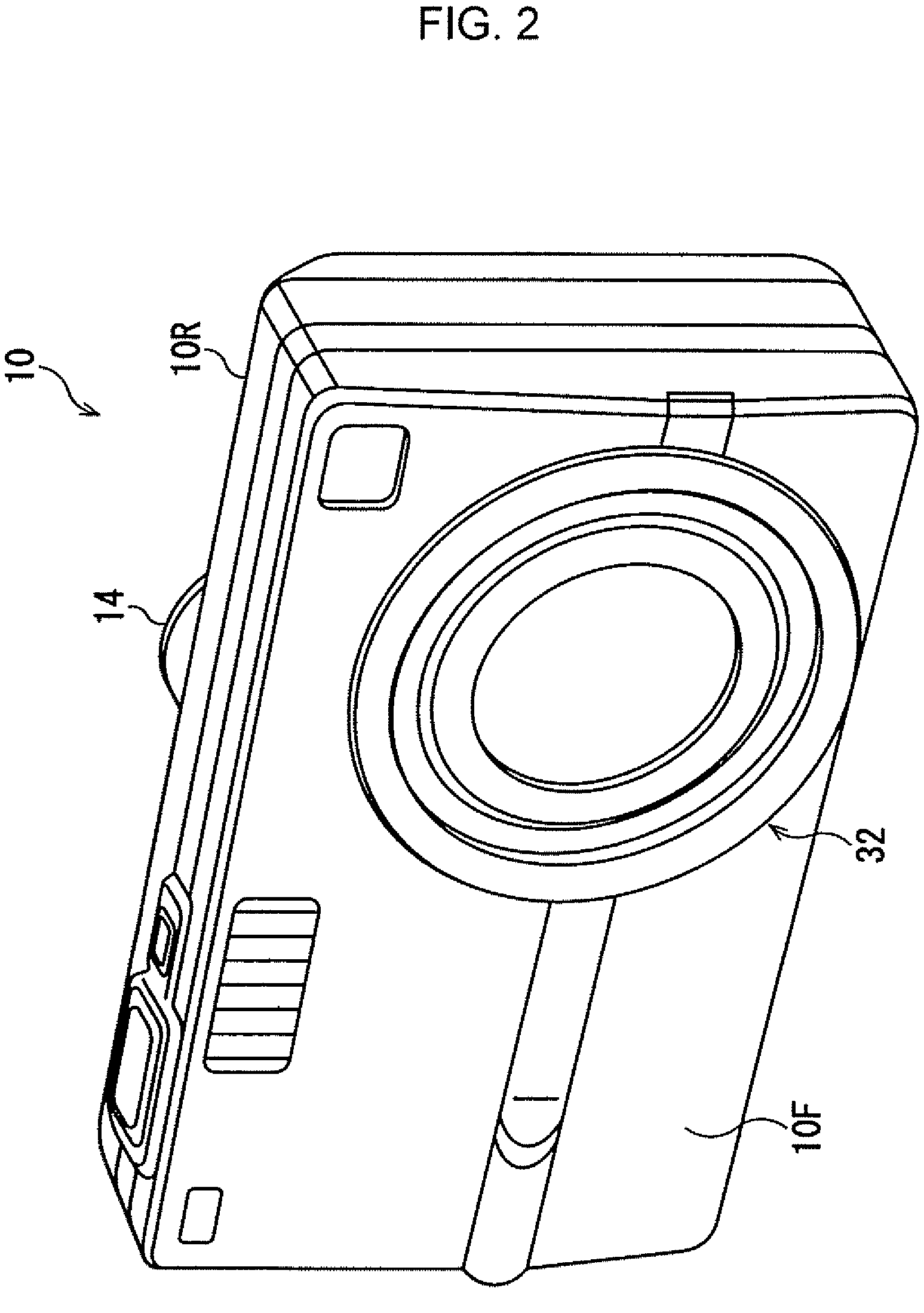
[0023]As shown in FIG. 1, in a digital camera 10, a lens barrel 32, including a photographing lens 12, is provided. The photographing lens 12 moves between an extended position, in which it is extended from a front surface 10F of the digital camera 10, and a housed position, in which it is inside the digital camera 10, where the photographing lens 12 becomes invisible from the outside (see FIG. 2).

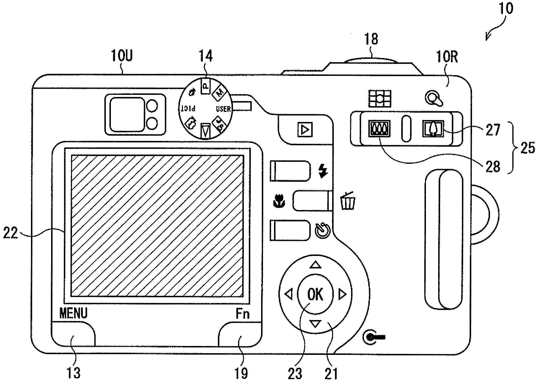
[0024]A mode dial 14 is provided on a rear surface 10R of the digital camera 10. A predetermined mode is selected by the operation of the mode dial 14. When a mode where the photographing lens 12 is not used, is selected, the photographing lens 12 is caused to be moved to the housed position for protecting the photographing lens 12.

[0025]As shown in FIG. 3, on the rear surface 10R, a menu button 13, an Fn button 19, a cross key 21, an OK button 23, and a zoom switch 25 ...


PUM


Abstract

A mode dial mechanism for a photographing device comprising a photographing lens, according to the present invention, includes a lens mover, a mode dial, and a mode judge. The lens mover moves the photographing lens. The mode dial is for selecting a mode from a plurality of modes, including a lens housing mode where the photographing lens is housed in a housed position which is inside the photographing device. The mode judge determines whether the lens housing mode should be set or not, when the lens housing mode is selected. When the mode judge determines that the lens housing mode should be set, the lens housing mode is set, and the lens mover moves the photographing lens to the housed position.

Description

BACKGROUND OF THE INVENTION[0001]1. Field of the Invention[0002]The present invention relates to a mode-setting device, and especially relates to a mode-setting device for photographing devices, such as cameras.[0003]2. Description of the Related Art[0004]Generally, in photographing devices such as cameras and video recorders, various photographing modes and so on can be selected or set. A mode dial, as a mode-setting device, has been used for selecting a desired mode from a plurality of selectable modes. On mode dials, generally, a plurality of selectable modes are marked, and a user moves a mode dial to set a mark of a selecting mode to be in a predetermined rotation position.[0005]On the other hand, in some photographing devices, a photographing lens is automatically housed, when a predetermined mode is selected for protecting the photographing lens.[0006]In case a mode where a photographing lens should not be housed is selected, the photographing lens can be housed once, and the...

Claims


Application Information

Patent Timeline
Patent Type & Authority Patents(United States)
IPC IPC(8): G03B5/02
CPCH04N5/2252H04N5/232H04N5/23245H04N2101/00H04N23/51H04N23/667H04N23/631
Inventor MAEDA, HIROKAZU
Owner RICOH IMAGING COMPANY
Why Eureka
Try Eureka