Developer cartridge, image carrier unit, and image forming apparatus

a development cartridge and image carrier technology, applied in the direction of electrographic process apparatus, instruments, optics, etc., can solve the problems of relatively complicated apparatus structure, and achieve the effects of simple construction, excellent operability, and convenient and secure retention

Active Publication Date: 2009-04-28
BROTHER KOGYO KK
View PDF5 Cites 99 Cited by
  • Summary
  • Abstract
  • Description
  • Claims
  • Application Information

AI Technical Summary

Benefits of technology

[0010]Therefore, it is an object of the present invention to provide a developer cartridge which can be easily and securely retained by an image carrier unit in a simple construction as well as excellent in operability, an image carrier unit to which the developer cartridge is detachably attached, and an image forming apparatus to which the developer cartridge and the image carrier unit are detachably attached.

Problems solved by technology

Moreover, a dedicated component, such as fixed lever, is provided to retain the developer cartridge with the photosensitive member cartridge, whereby the mechanism of the apparatus may become relatively complicated.

Method used


Image

  • Developer cartridge, image carrier unit, and image forming apparatus
  • Developer cartridge, image carrier unit, and image forming apparatus
  • Developer cartridge, image carrier unit, and image forming apparatus

Examples


first embodiment

1. General Structure of Color Laser Printer

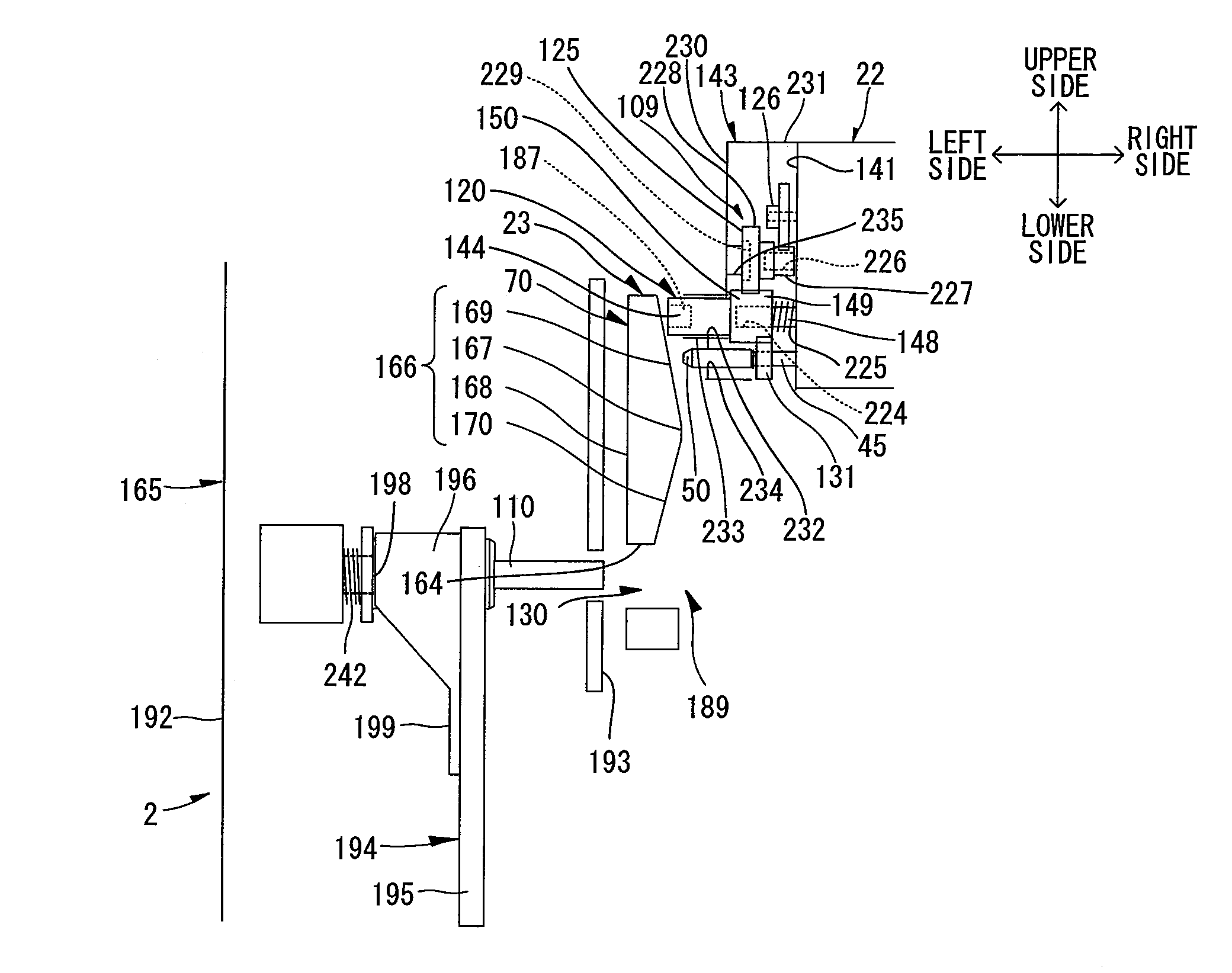
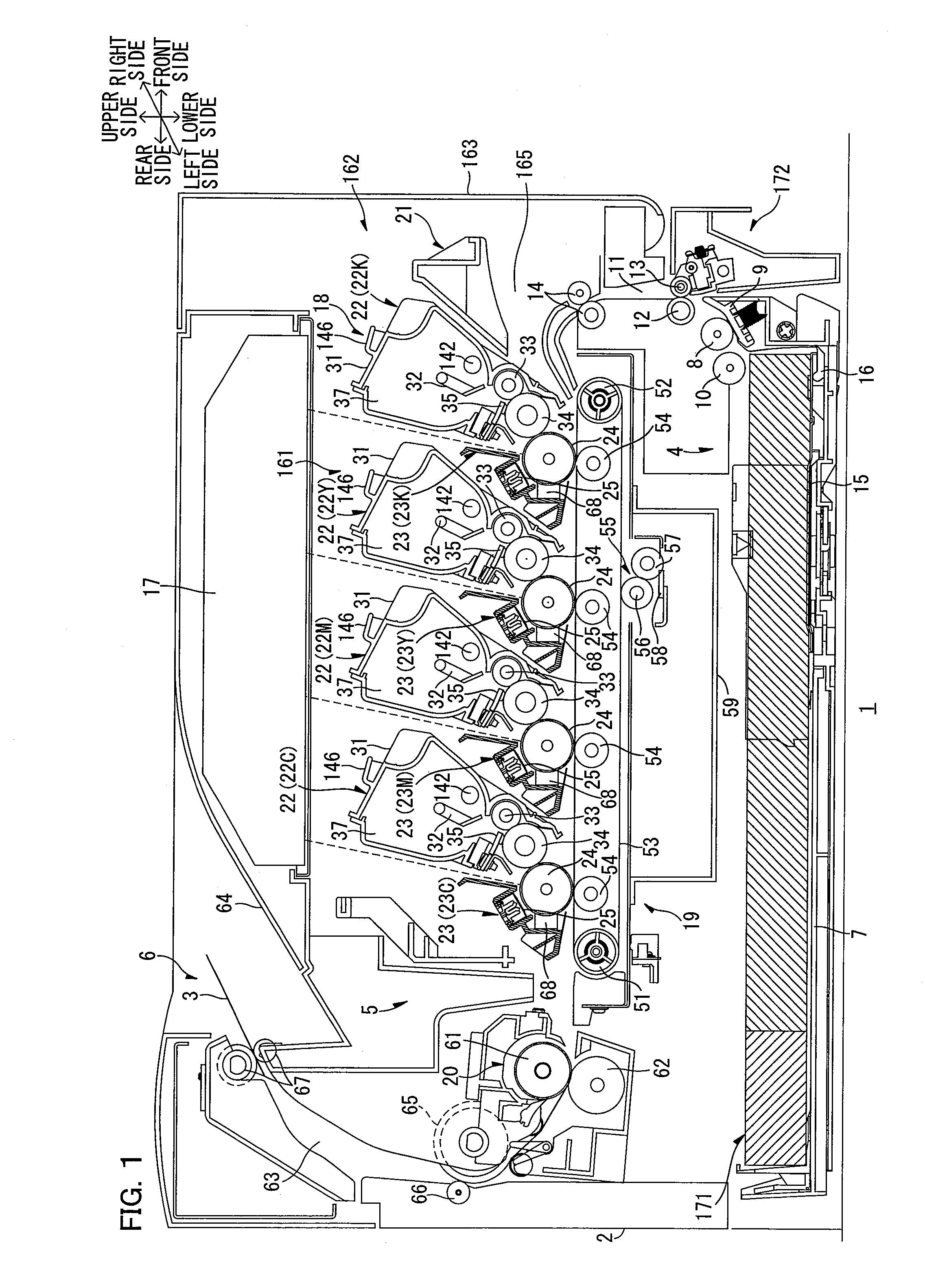
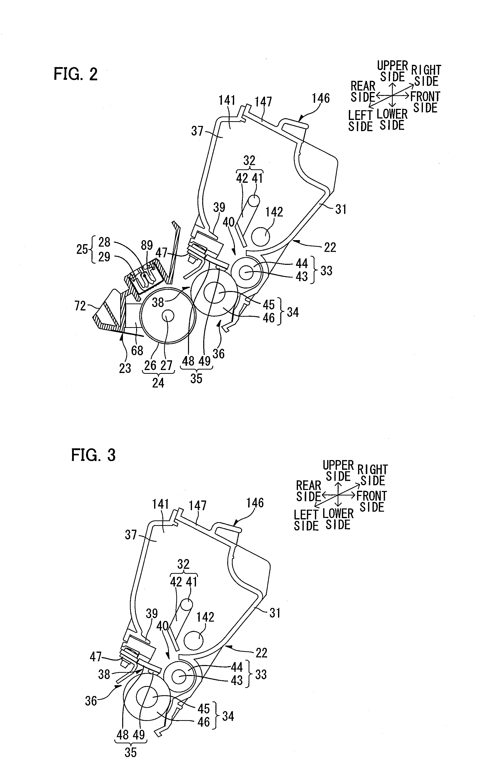
[0034]FIG. 1 is a side sectional view of the major portion of a color laser printer serving as an image forming apparatus according to one embodiment of the present invention; FIG. 2 is a side sectional view of the major portion of a drum subunit attached with a developer cartridge of the color laser printer shown in FIG. 1; and FIG. 3 is a side sectional view of the major portion of the developer cartridge shown in FIG. 2.

[0035]As shown in FIG. 1, the color laser printer 1 is of a horizontal-tandem type, in which a plurality of drum subunits 23 (described later) serving as an image carrier unit are horizontally arranged in juxtaposition. The color laser printer 1 includes a sheet feeding section 4 for feeding a sheet 3 as a recording medium, an image forming section 5 for forming images on the sheet 3 fed by the sheet feeding section 4, and a sheet ejecting section 6 for ejecting the sheet 3 with an image formed thereon, in a main body cas...

second embodiment

[0308]The first embodiment mentioned above shows as an example the color laser printer 1 of a tandem type for directly transferring toner images onto a sheet 3 from each photosensitive drum 24. However, the present invention is not limited thereto, and can be constituted, for example, as a color laser printer of an intermediate transfer type in which toner images for respective colors are once transferred to an intermediate transfer body from respective photosensitive members, and thereafter, transferred onto a sheet by one operation. Furthermore, the printer can be constituted as a monochrome laser printer. The monochrome laser printer may include a process unit as an image forming unit in which a single developer cartridge 22 is attached in a single drum subunit 23.

[0309]In the above explanation, two independent embodiments of the first and the second to which the present invention is applied, have been explained in detail. However, it is possible for those skilled in the art to o...


PUM


Abstract

The present invention provides a developer cartridge detachably attachable to a casing of an image carrier unit, includes a developing roller and a first rotation body that rotates the developing roller by coupling to a second rotation body provided in an image forming apparatus body with the developer cartridge attached in the casing. The first rotation body is configured to advance and retract with respect to a side wall of the casing which extends along an attachment / detachment direction of the developer cartridge, and is normally urged in an advance direction. A downstream end portion of the first rotation body in the advance direction is arranged downstream in the advance direction from an upstream end of the side wall in the advance direction with the developer cartridge attached in the casing.

Description

CROSS REFERENCE TO RELATED APPLICATION[0001]This application claims priority benefits on the basis of Japanese Patent Application No. 2006-81445 filed on Mar. 23, 2006, the disclosure of which is incorporated herein by reference.BACKGROUND OF THE INVENTION[0002]1. Field of the Invention[0003]The present invention relates to an image forming apparatus such as a laser printer, and to an image carrier unit detachable to the image forming apparatus, and to a developer cartridge detachable to the image carrier unit.[0004]2. Description of the Related Art[0005]As for an image forming apparatus such as a laser printer, there have been known, for example, a color image forming apparatus having a plurality of developer cartridges for giving a toner onto a surface of a photosensitive drum in a photosensitive member cartridge, each of the developer cartridges being detachably arranged in juxtaposition (see, for example, Japanese Unexamined Patent Publication No. 2003-015378).[0006]In the color...

Claims


Application Information

Patent Timeline
Patent Type & Authority Patents(United States)
IPC IPC(8): G03G21/16
CPCG03G21/1647G03G21/1676G03G2221/163G03G2221/1657G03G2221/1684
Inventor SHIRAKI, MASATOSHI
Owner BROTHER KOGYO KK
Why Eureka
Try Eureka