
Method of increasing the capacity of enhanced data channel on uplink in a wireless communications system

a wireless communications system and enhanced data technology, applied in the field of wireless communications, can solve the problems of reducing the overall capacity of the reverse channel, unable to predict whether the ue will send a new transmission of another frame, and often assigning low data rates, so as to achieve the effect of greatly increasing the capacity of applications using the enhanced uplink data channel and significantly reducing the power of the e-dpcch

Active Publication Date: 2009-04-28
WSOU INVESTMENTS LLC
View PDF5 Cites 15 Cited by
  • Summary
  • Abstract
  • Description
  • Claims
  • Application Information

AI Technical Summary

Benefits of technology

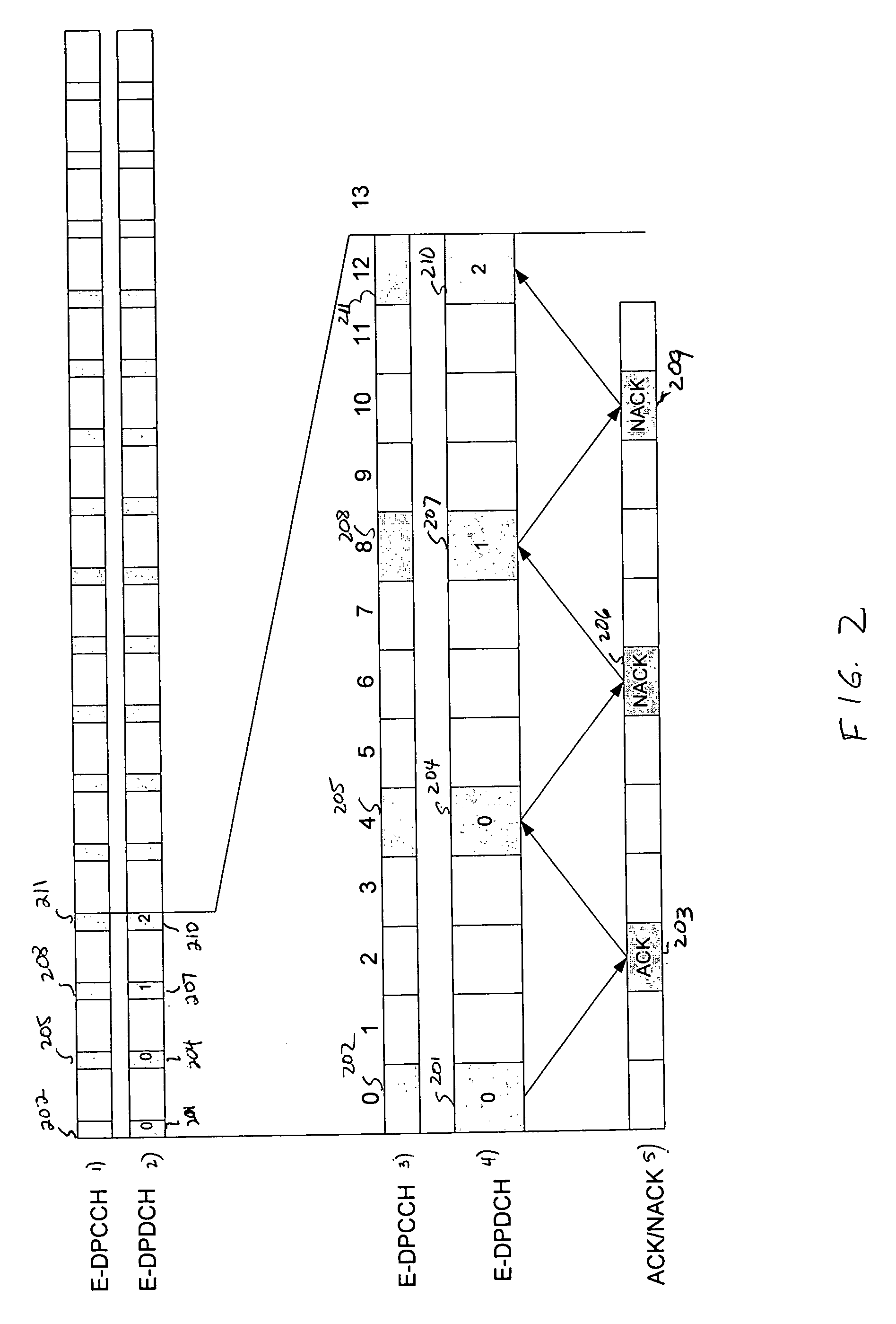
[0008]In accordance with an embodiment of the present invention, E-DPCCH power is significantly reduced and the capacity for applications using the enhanced uplink data channel is thus greatly increased by transmitting E-DPCCH in association with a corresponding E-DPDCH transmission only selectively and not transmitting E-DPCCH at other times. To that end, E-DPCCH is only transmitted when at least one predetermined “start criterion” is met and is turned off when a predetermined “stop criterion” is met and remains off until a “start criterion” is later met again. Specifically, E-DPCCH is transmitted when a frame being transmitted on the corresponding E-DPDCH differs in the transport format combination from the E-DPDCH frame previously transmitted within the same HARQ process. Transmission of E-DPCCH is continued until a notification is received that one or more NodeBs to which the transmitting UE has successfully decoded at least one frame, where upon such notification, transmission of E-DPCCH is stopped.
[0011]A third embodiment is a modification of the first embodiment in that E-DPCCH continues to be transmitted until all NodeBs that the UE is transmitting to return a positive acknowledgment that they have successfully decoded at least one E-DPDCH frame. Upon receiving all acknowledgments, the UE switches off E-DPCCH transmission. In this embodiment, however, when E-DPCCH is turned off the UE also sends a new-transmission flag of minimum bit length, such as a single bit flag, referred to as new-transmission-flag (new-tx-flag), to the NodeBs only when a new E-DPDCH frame is being transmitted for the first time. Thus, if NodeB does not detect the E-DPCCH transmission, but does detect the new-tx-flag, it uses the previous transport format combination and assumes the transmission on the E-DPDCH to be a new transmission (a redundancy version equal to 0). If NodeB does not detect the E-DPCCH transmission or the new-transmission flag, it adds one to the previous redundancy version and attempts to decode E-DPDCH using the previous transport format combination. The new-transmission flag can be transmitted from UE to NodeB by either adding a specific code word on the current E-DPCCH or by means of a separate physical code channel. This avoids the NodeB from having to attempt to decode a received E-DPDCH frame multiple times for each possible redundancy version, which function would otherwise need to be performed when an E-DPDCH frame is received without a corresponding E-DPCCH.

Problems solved by technology

Therefore, even if a NodeB was not able to decode a frame transmission previously, it cannot predict whether the UE will send a new transmission of another frame or the retransmission of the previous frame since the previous frame might have been acknowledged by another NodeB with which the UE was communicating.
In particular, very low data rates are often assigned to UEs with unfavorable path loss conditions in heavily loaded cells.
Disadvantageously, the additional power required for transmitting E-DPCCH can significantly reduce the overall capacity on the reverse channel.

Method used


Image

  • Method of increasing the capacity of enhanced data channel on uplink in a wireless communications system
  • Method of increasing the capacity of enhanced data channel on uplink in a wireless communications system
  • Method of increasing the capacity of enhanced data channel on uplink in a wireless communications system

Examples


Embodiment Construction

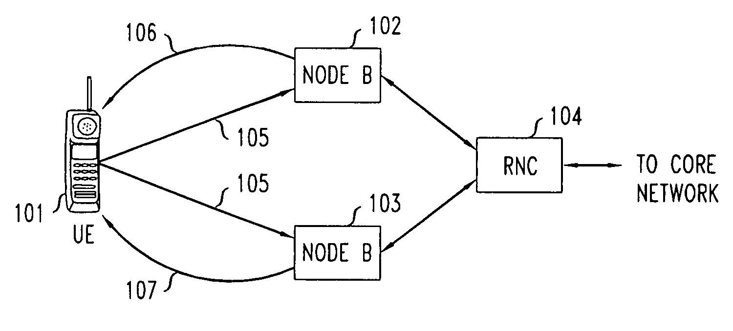
[0017]With reference to FIG. 1, UE 101 is shown communicating on the enhanced data channel in a soft handoff situation with both NodeB 102 and NodeB 103. NodeB 102 and NodeB 103 are illustratively shown connected to the same multi-NodeB (or multi-base station) controller 104, referred to herein and in UMTS terminology as an RNC (Radio Network Controller). For clarity purposes, connections of RNC 104 to the core network are not shown, but are understood to exist by those skilled in the art. The transmissions labeled 105 indicate that UE 101 is sending a frame on the uplink through E-DPDCH and E-DPCCH to NodeBs 102 and 103. Both NodeBs 102 and 103 independently attempt to decode the E-DPDCH and E-DPCCH transmissions. If the E-DPDCH frame is successfully decoded by either NodeB 102 or NodeB 103, the NodeB that decodes the frame sends a positive acknowledgment (ACK) to UE 101 by either transmission 106 from NodeB 102 or transmission 107 from NodeB 103. If UE 101 receives an ACK from eit...


PUM


Abstract

In a UMTS wireless communication system, the enhanced dedicated physical control channel (E-DPCCH) that is usually always transmitted together with the enhanced dedicated physical data channel (E-DPDCH) on the uplink from a UE to a NodeB is instead only transmitted when a predetermined “start criterion” is met and is turned off when a predetermined “stop criterion” is met until a “start criterion” is later met again. The UE starts transmitting E-DPCCH whenever the corresponding E-DPDCH transport format combination is different from the previous one in the same HARQ process or some other “start criterion” is met. Multiple mechanisms can be used to decide when the UE should switch off E-DPCCH transmission after the transport format combination of E-DPDCH has changed.

Description

CROSS-REFERENCE TO RELATED APPLICATIONS[0001]This application is related to co-pending U.S. patent application Ser. No. 11 / 190,617, filed Jul. 27, 2005.TECHNICAL FIELD[0002]This invention relates to wireless communications.BACKGROUND OF THE INVENTION[0003]A wireless communications network typically includes a variety of communication nodes coupled by wireless or wired connections and accessed through different types of communications channels. Each of the communication nodes includes a protocol stack that processes the data transmitted and received over the communications channels. Depending on the type of communications system, the operation and configuration of the various communication nodes can differ and are often referred to by different names. Such communications systems include, for example, a Code Division Multiple Access 2000 (CDMA2000) system and a Universal Mobile Telecommunications System (UMTS).[0004]Third generation wireless communication protocol standards (e.g., 3GP...

Claims


Application Information

Patent Timeline
Patent Type & Authority Patents(United States)
IPC IPC(8): H04B7/00G01R31/08H04W52/02
CPCH04L1/0025H04L1/1812H04W52/0216Y02D30/70H04W24/00H04W28/18
Inventor BACHL, RAINER WALTERRAO, ANIL MSCHACHT, MIRKOYE, HENRY HUI
Owner WSOU INVESTMENTS LLC
Learn More