
Variable dust chute for circular saws

a circular saw and dust chute technology, applied in the field of hand-held circular saws, can solve the problems of woodworkers spending an inordinate amount of time cleaning up the work area, the dust generated during the use of rotary power tools is a major problem, and the user's airway irritation or possible explosion,

Inactive Publication Date: 2009-05-05
BLACK & DECKER INC
View PDF13 Cites 57 Cited by
  • Summary
  • Abstract
  • Description
  • Claims
  • Application Information

AI Technical Summary

Benefits of technology

[0007]Accordingly, the present invention is directed to a hand-held circular saw with an integrated dust collection system. As such, the dust collection system allows dust and debris to be collected in a dust collection receptacle, directed away from the user, or circulated through the upper blade guard of the circular saw.

Problems solved by technology

Saw dust generated during use of rotary power tools is a major problem.
First, such dust may cause user airway irritation or possible explosion if ignited by a flame or a spark.
In addition, saw dust is very difficult to clean-up and as such, results in the woodworker spending an inordinate amount of time cleaning up the work area.
Further, saw dust generated while making a cut may impair user visibility of a work piece and thus, decreased cut precision.
However, such device does not assist the woodworker in decreasing the amount of time associated with clean-up or visibility of the work piece.
Although dust collection systems presently known in the art have greatly reduced the possibility of user airway irritation and amount of clean-up associated with the use of rotary power tools as well as enhanced user visibility, many limitations are still associated with such systems.
A central dust collection system, for instance, is often quite large, expensive to purchase and may require modifications to be made to the work area (i.e. addition of a 220V electrical supply and ductwork) prior to operation.
Further, an individual dust collection system which is a component of a particular tool (i.e. a hand-held circular saw) is limited by the need to attach a vacuum hose to the dust port confining user movement of the saw and negating the benefit of a cordless tool.

Method used


Image

  • Variable dust chute for circular saws
  • Variable dust chute for circular saws
  • Variable dust chute for circular saws

Examples


Embodiment Construction

[0022]Reference will now be made in detail to the presently preferred embodiments of the invention, examples of which are illustrated in the accompanying drawings.

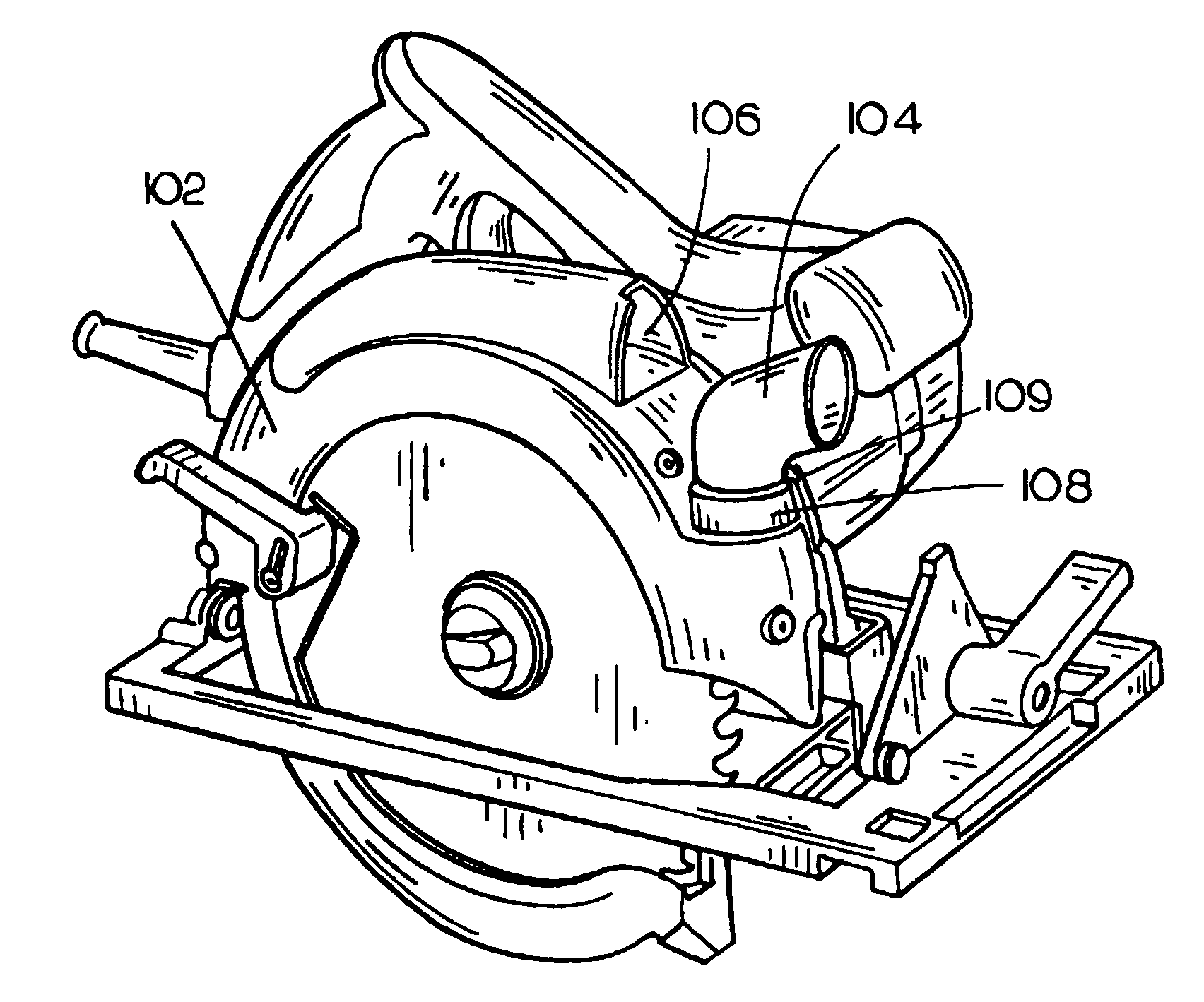
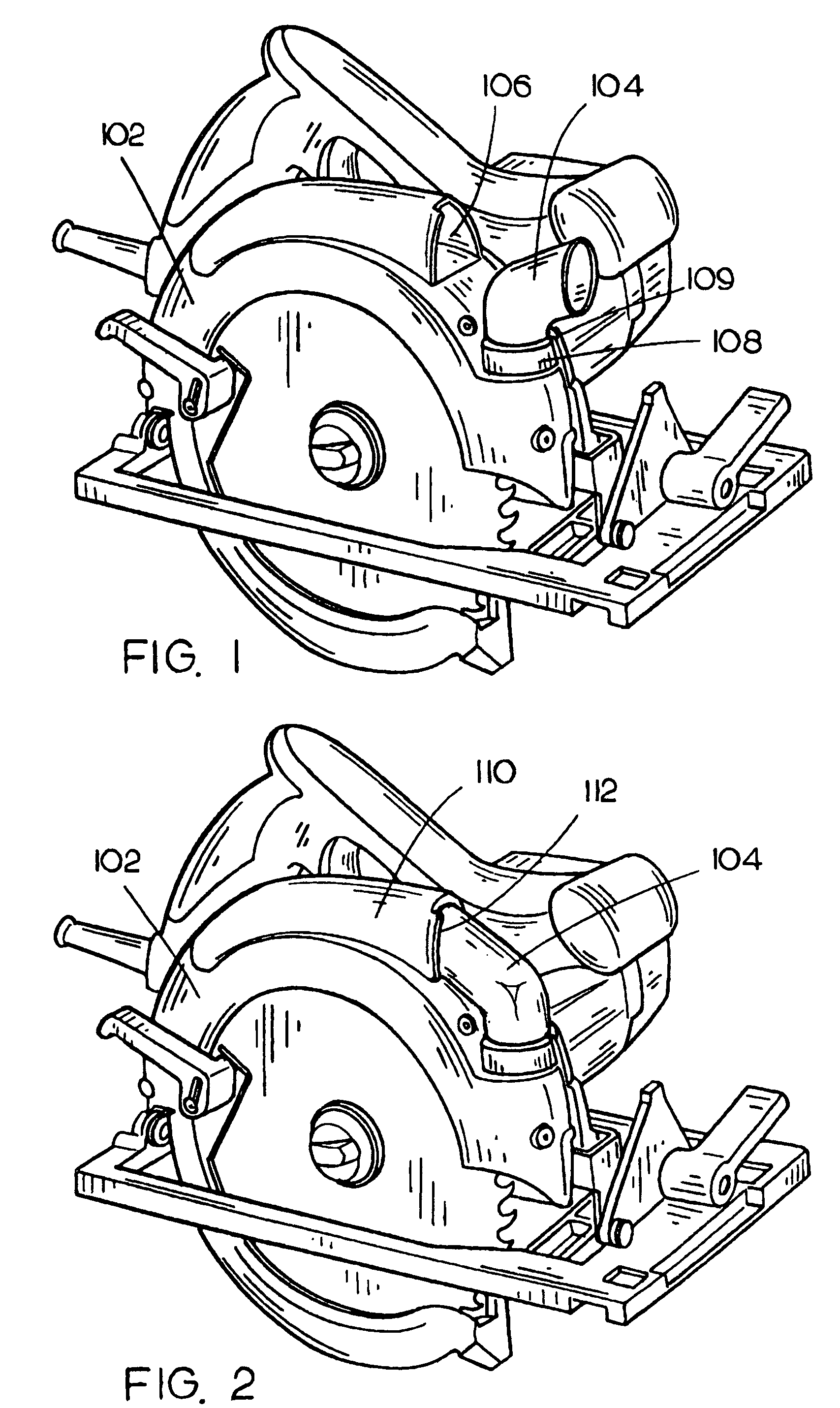
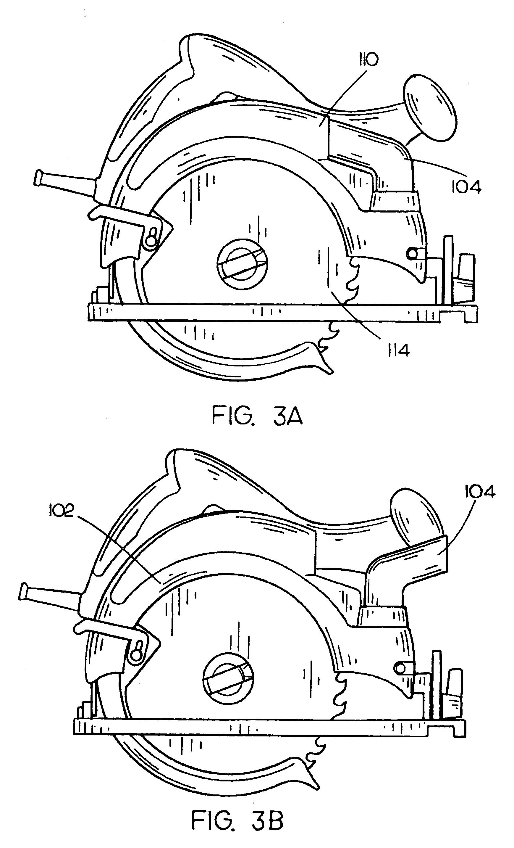
[0023]FIG. 1 illustrates a hand-held circular saw with an integrated dust collection system in accordance with an exemplary embodiment of the present invention. Such saw includes an upper blade guard 102 for protecting the user from a saw blade and a dust collection system including a dust chute 104 to allow dust and debris to be directed away from the user. In the embodiment illustrated, upper blade guard 102 has a front region and a back region. Further, the dust chute 104 is disposed within the front region of the upper blade guard, includes a pivot mechanism 108 and is substantially conformed to the contour of the upper blade guard.

[0024]In the present embodiment, the dust chute 104 is in the first position in which the dust and debris may be either directed away from the user or collected. The dust chute 104 is locked...


PUM

PropertyMeasurementUnit
vacuumaaaaaaaaaa
shapeaaaaaaaaaa

Abstract

The present invention is directed to a hand-held circular saw with an integrated dust collection system. Such saw may include an upper blade guard for protecting the user from a saw blade, the upper blade guard configured with a front region and a back region, the front region including a hollow channel to control the pathway of dust and debris and a dust collection system incorporated within the front region of the upper blade guard allowing dust and debris to be directed away from the user.

Description

CROSS-REFERENCE TO RELATED APPLICATIONS[0001]The present application claims the benefit under 35 U.S.C. § 119(e) of U.S. Provisional Application Ser. No. 60 / 516,143, filed Oct. 31, 2003. Said U.S. Provisional Application Ser. No. 60 / 516,143 is herein incorporated by reference in its entirety.FIELD OF THE INVENTION[0002]The present invention generally relates to the field of hand-held circular saws, and more particularly to a hand-held circular saw with an integrated dust collection system.BACKGROUND OF THE INVENTION[0003]Saw dust generated during use of rotary power tools is a major problem. First, such dust may cause user airway irritation or possible explosion if ignited by a flame or a spark. In addition, saw dust is very difficult to clean-up and as such, results in the woodworker spending an inordinate amount of time cleaning up the work area. Further, saw dust generated while making a cut may impair user visibility of a work piece and thus, decreased cut precision. Therefore, ...

Claims


Application Information

Patent Timeline
Patent Type & Authority Patents(United States)
IPC IPC(8): B27B9/00B27G3/00
CPCB23D59/006B27B9/00
Inventor SCHNELL, JOHN W.ETTER, MARK A.HARR, DEBBIEGIST, LESLIE D.
Owner BLACK & DECKER INC
Learn More