Apparatus and method for measuring a parameter of a multiphase flow

a multi-phase flow and measurement apparatus technology, applied in the direction of measurement devices, volume/mass flow by dynamic fluid flow effect, instruments, etc., can solve the problems of small size, inability to ensure, and inability to accurately measure the volumetric flow ra

Active Publication Date: 2009-05-05
EXPRO METERS
View PDF164 Cites 31 Cited by
  • Summary
  • Abstract
  • Description
  • Claims
  • Application Information

AI Technical Summary

Problems solved by technology

Unfortunately however, large amounts of hydrocarbons tend to be present in crude oil and as such, during transport between the well heads and the refineries the crude oil has a propensity to ‘out gas’ during transport resulting in small, unknown levels of entrained gases being present at the fiscal measurement locations.
This is undesirable for at least two (2) reasons.
First, because the effect of the entrained gases on most known liquid volumetric technologies results in an over reporting of the liquid component flow rate by an amount equal to the volume of the entrained gases, the measured volumetric flow rate is typically inaccurate.
Unfortunately, however, while most standards for fiscal volumetric flow of liquids require that the liquid be completely devoid of gases, a problem arises when it becomes impractical to ensure that the liquid stream in question is indeed completely devoid of free gases.
This is because although the gas volume fraction (GVF) level is typically less than 1%, it is often the primary source of error in the fiscal measurement.
Second, because the complete separation of the gas and liquid phases cannot be ensured, the liquid volume determination is also typically inaccurate resulting in inaccurate watercut values.
Accuracy of oil production measurement is limited to three constraints.
One constraint involves the inability to ensure the complete separation of gas and liquid flow.
This constraint results in an inaccurate liquid volume determination, inaccurate gas volume determination and an inaccurate watercut determination.
The second constraint involves the relatively low number of flow measurements available due to maintenance requirements, installation requirements and pressure drop in the point with any increase in measurement points.
The third constraint involves the very low number of watercut measurement points, which is due to the reliability of the watercut measurement devices and the calibration requirements of the meters.

Method used


Image

  • Apparatus and method for measuring a parameter of a multiphase flow
  • Apparatus and method for measuring a parameter of a multiphase flow
  • Apparatus and method for measuring a parameter of a multiphase flow

Examples


Embodiment Construction

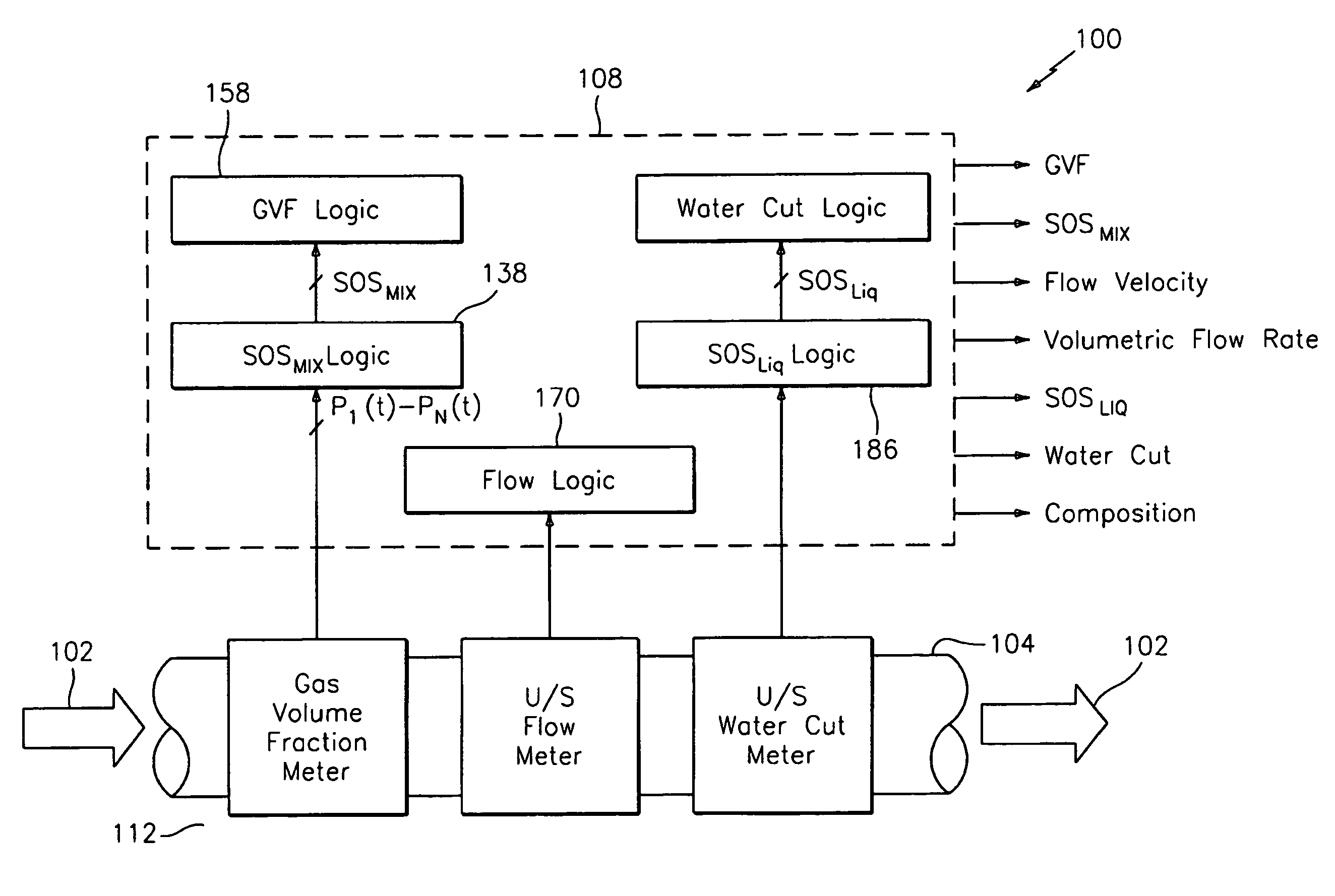
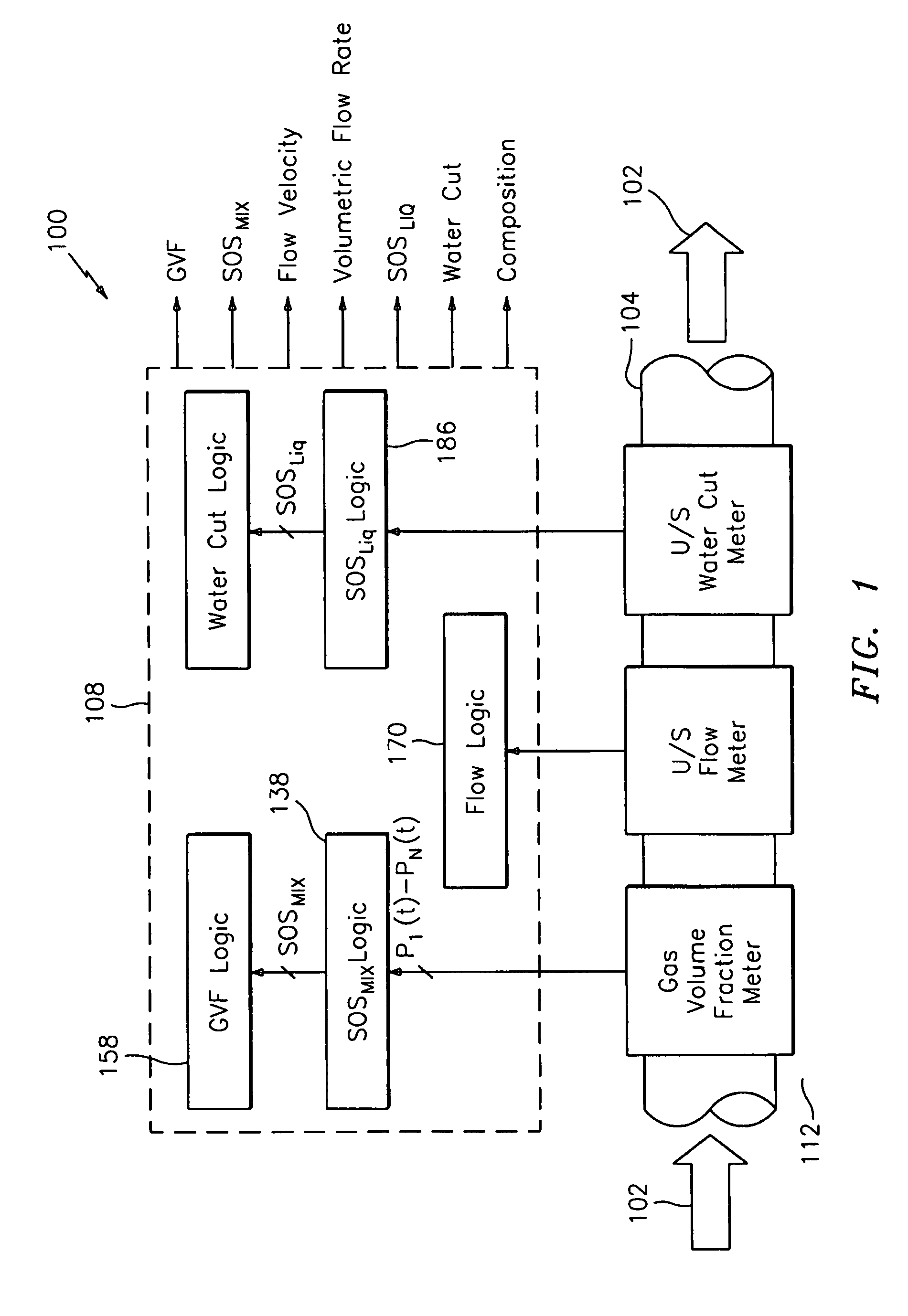
[0028]FIG. 1 illustrates a block diagram of a flow measurement device 100 for measuring a parameter of a multiphase flow 102 passing through a pipe 104. The multiphase flow or mixture 102 includes any mixture having any combination of a gas, liquid, or solid phase and while the present invention is particularly useful in measuring multiphase flows, it should be appreciated that the apparatus 100 can also measure a parameter of a single phase flow. As discussed hereinbefore, the apparatus embodying the present invention is useful in measuring a multiphase flow comprising oil, water and gas. The description of the present invention will therefore assume that the mixture is a combination of oil, water, and gas, however, the invention contemplates that any single or multiphase flow can be measured.

[0029]As shown in FIG. 1, the apparatus 100 functions as a gas volume fraction (or void fraction) meter, an ultrasonic flow meter, and an ultrasonic watercut meter. The gas volume fraction (GV...


PUM


Abstract

An apparatus is provided that determines a characteristic of a multiphase fluid, such as an aerated oil and water fluid, flowing within a pipe. The apparatus includes a fluid flow meter, a water cut meter, and a density meter, wherein the density meter determines the density of the fluid flow to determine the gas volume (or void) fraction of the multiphase fluid flow. The output signal of each of the meters is provided to a multiphase flow model to provide a plurality of multiphase parameters, such as phase fraction, volumetric flow, mass flow of each of the phases of the multiphase mixture, optimized for various flow conditions. Each of the meters may be secured to the outer surface of the pipe using various means, such a clamping means.

Description

CROSS-REFERENCE TO RELATED PATENT APPLICATIONS[0001]This application is a continuation in part of U.S. patent application Ser. No. 11 / 442,954, filed May 30, 2006, which claimed the benefit of U.S. Provisional Application No. 60 / 685,532 filed May 27, 2005; and U.S. Provisional Application No. 60 / 736,684, filed Nov. 14, 2005; and claims the benefit of U.S. Provisional Patent Application No. 60 / 758,242 filed Jan. 10, 2006, which are incorporated herein by reference in their entirety.TECHNICAL FIELD[0002]This invention relates to an apparatus for measuring a parameter of a process flow passing within a pipe, and more particularly to a flow measurement apparatus having ultrasonic sensors and an array of strain-based sensors and for processing data signals therefrom to provide an output indicative of the speed of sound propagating through the process flow and / or a flow parameter of the process flow passing through a pipe.BACKGROUND ART[0003]In industrial applications that involve flowing ...

Claims


Application Information

Patent Timeline
Patent Type & Authority Patents(United States)
IPC IPC(8): G01F1/32
CPCG01F1/667G01F1/668G01F1/74G01F15/005
Inventor GYSLING, DANIEL L.VAN DER SPEK, ALEX
Owner EXPRO METERS
Why Eureka
Try Eureka