Heat exchanger with multiple stage fluid expansion in header

a technology of fluid expansion and heat exchanger, which is applied in the direction of mechanical equipment, refrigeration components, lighting and heating apparatus, etc., can solve the problems of significantly reducing heat exchanger efficiency, adversely affecting heat exchanger efficiency, and two-phase maldistribution, etc., and achieves small pressure drop, large pressure drop, and small pressure drop in refrigerant flow.

Inactive Publication Date: 2009-05-05
CARRIER CORP
View PDF46 Cites 14 Cited by
  • Summary
  • Abstract
  • Description
  • Claims
  • Application Information

AI Technical Summary

Benefits of technology

[0012]It is a general object of the invention to reduce maldistribution of fluid flow in a heat exchanger having a plurality of multi-channel tubes extending between a first header and a second header.
[0013]It is an object of one aspect of the invention to reduce maldistribution of refrigerant flow in a refrigerant vapor compression system heat exchanger having a plurality of multi-channel tubes extending between a first header and a second header.
[0019]In an embodiment, the second heat exchanger includes a connector having an inlet end and an outlet end and defining an inlet chamber at its inlet end, an outlet chamber at its outlet end, and an intermediate chamber defining a flow path between the inlet chamber and the outlet chamber. The inlet chamber of the connector is in fluid flow communication with the first header and the outlet chamber is in fluid flow communication the plurality of discrete fluid flow paths of the heat exchange tube. The flow path includes a plurality of flow restriction ports disposed therein in a spaced series arrangement and adapted to create a relatively large pressure drop in refrigerant flow passing in the first direction and a relatively small pressure drop in refrigerant flow passing in the second direction.
[0020]In an embodiment, the first heat exchanger includes a connector having an inlet end and an outlet end and defining an inlet chamber at its inlet end in fluid flow communication with the fluid chamber of the second header, an outlet chamber at its outlet end in fluid communication with the plurality of discrete fluid flow paths of the at least one heat exchange tube, and an intermediate chamber defining a flow path between the inlet chamber and the outlet chamber. The flow path includes a plurality of flow restriction ports disposed therein in a spaced series arrangement and adapted to create a relatively small pressure drop in refrigerant flow passing in the first direction and a relatively large pressure drop in refrigerant flow passing in the second direction.

Problems solved by technology

Non-uniform distribution, also referred to as maldistibution, of two-phase refrigerant flow is a common problem in parallel tube heat exchangers which adversely impacts heat exchanger efficiency.
Among other factors, two-phase maldistribution problems are caused by the difference in density of the vapor phase refrigerant and the liquid phase refrigerant present in the inlet header due to the expansion of the refrigerant as it traversed the upstream expansion device.
Obtaining uniform refrigerant flow distribution amongst the relatively large number of small cross-sectional flow area refrigerant flow paths is even more difficult than it is in conventional round tube heat exchangers and can significantly reduce heat exchanger efficiency.

Method used


Image

  • Heat exchanger with multiple stage fluid expansion in header
  • Heat exchanger with multiple stage fluid expansion in header
  • Heat exchanger with multiple stage fluid expansion in header

Examples


Embodiment Construction

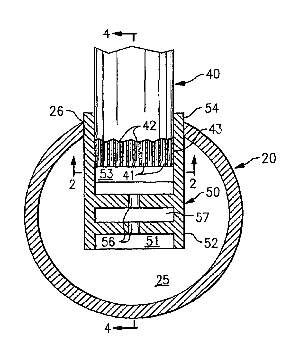
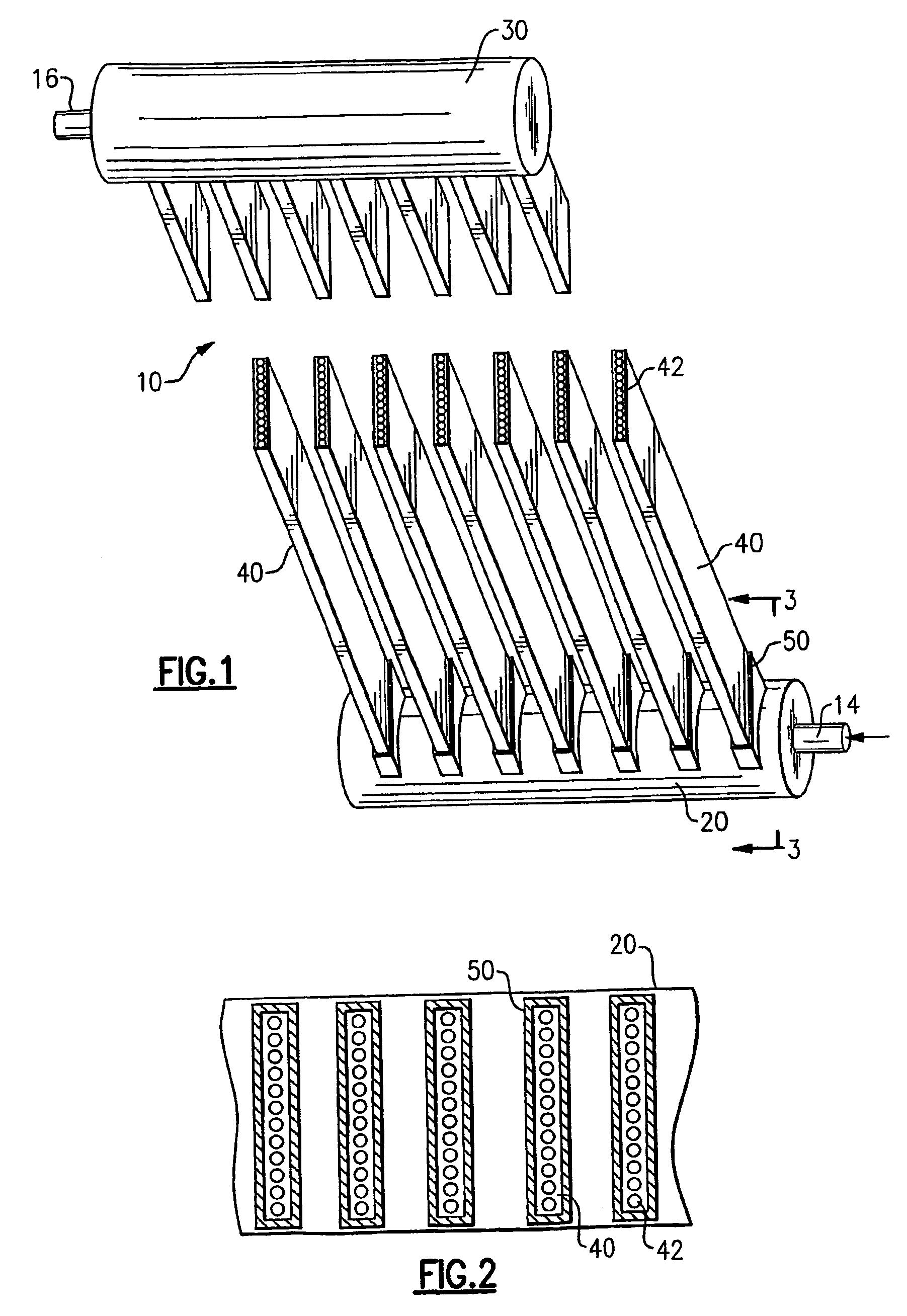
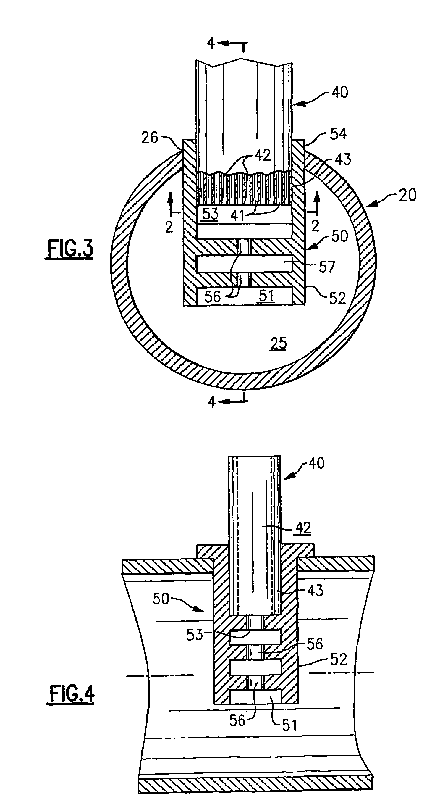
[0036]The heat exchanger 10 of the invention will be described in general herein with reference to the illustrative single pass, parallel-tube embodiment of a multi-channel tube heat exchanger as depicted in FIGS. 1 and 2. In the illustrative embodiment of the heat exchanger 10 depicted in FIGS. 1 and 2, the heat exchange tubes 40 are shown arranged in axially spaced, parallel relationship extending generally vertically between a generally horizontally extending inlet header 20 and a generally horizontally extending outlet header 30. However, the depicted embodiment is illustrative and not limiting of the invention. It is to be understood that the invention described herein may be practiced on various other configurations of the heat exchanger 10. For example, the heat exchange tubes may be arranged in parallel relationship extending generally horizontally between a generally vertically extending inlet header and a generally vertically extending outlet header. As a further example, ...


PUM


Abstract

A heat exchanger includes a plurality of flat, multi-channel heat exchange tubes extending between spaced headers. Each heat exchange tube has an inlet end in fluid flow communication with one of the headers and an outlet opening to the other header. Each heat exchange tube has a plurality of flow channels extending longitudinally in parallel relationship from its inlet end to its outlet end. A plurality of connectors are positioned between the inlet header and the heat transfer tubes to define a flow path providing fluid flow communication between the inlet header and the inlet ends of the heat exchange tubes. Two or more flow restriction ports are arranged in the series in the flow path through each connector whereby fluid flowing from the inlet header to the flow channels of the heat exchange tube associated therewith undergoes an expansion as the fluid passes through each flow restriction port.

Description

CROSS-REFERENCE TO RELATED APPLICATION[0001]Reference is made to and this application claims priority from and the benefit of U.S. Provisional Application Ser. No. 60 / 649,268, filed Feb. 2, 2005, and entitled MINI-CHANNEL HEAT EXCHANGER WITH MULTI-STAGE EXPANSION DEVICE, which application is incorporated herein in its entirety by reference.FIELD OF THE INVENTION[0002]This invention relates generally to heat exchangers having a plurality of parallel tubes extending between a first header and a second header, also sometimes referred to as manifolds, and, more particularly, to providing fluid expansion within the header of a heat exchanger for improving distribution of two-phase flow through the parallel tubes of the heat exchanger, for example a heat exchanger in a refrigerant compression system.BACKGROUND OF THE INVENTION[0003]Refrigerant vapor compression systems are well known in the art. Air conditioners and heat pumps employing refrigerant vapor compression cycles are commonly us...

Claims


Application Information

Patent Timeline
Patent Type & Authority Patents(United States)
IPC IPC(8): F28F9/22
CPCF25B39/028F25B41/06F28F1/022F28F9/0202F28F9/028F25B13/00F25B2341/0662F25B41/39F28F9/04F28F9/02F28F1/02
Inventor GORBOUNOV, MIKHAIL B.SANGIOVANNI, JOSEPH J.VAISMAN, IGOR B.
Owner CARRIER CORP
Why Eureka
Try Eureka