Roller blind system for a sliding roof

a technology of roller blinds and sliding roofs, which is applied in the direction of doors/windows, roofs, and movable grilles, etc., can solve the problems of changing the operating force of the guide rail, the deviation of the operating force of the roller blind in the guide rail, so as to minimize the variance of the roller blind during the shifting

Inactive Publication Date: 2009-05-12
ROOF SYST GERMANY
View PDF6 Cites 8 Cited by
  • Summary
  • Abstract
  • Description
  • Claims
  • Application Information

AI Technical Summary

Benefits of technology

[0008]According to a still further embodiment of the invention, the compensation spring acts on the roller blind coil. This makes it possible to exert a frictional force on the roller blind coil that is dependent on a diameter of the roller blind coil, so that operating forces are obtained in total which minimizes variance during shifting of the roller blind.

Problems solved by technology

It has turned out, however, that operational forces required for shifting the roller blind in the guide rail change depending on the shifting direction.
In addition, it has turned out that operating forces, when the roller blind is moved toward a more closed position, become larger with an increasing extraction length of the roller blind.
Different and / or changing operating forces generally are perceived by a user as an annoyance.

Method used


Image

  • Roller blind system for a sliding roof
  • Roller blind system for a sliding roof
  • Roller blind system for a sliding roof

Examples


first embodiment

[0025]the roller blind system according to the invention will now be described on the basis of FIGS. 5 and 6. The same reference numerals will be used for the components which are known from FIGS. 1 to 4, and reference is made to the above explanations.

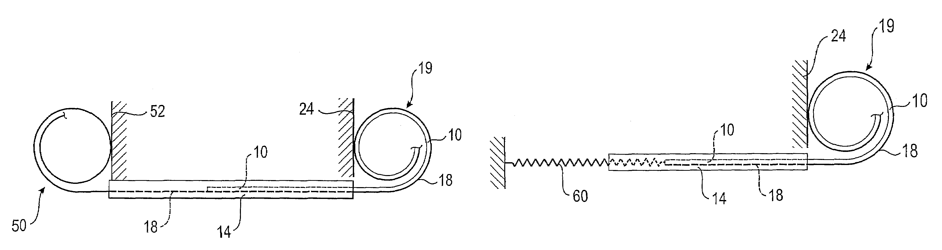
[0026]The embodiment according to FIGS. 5 and 6 is distinguished in that the spring steel bands 18 are extended beyond a front end of the roller blind 10 and a front end of the guide rails 14, so that an auxiliary coil 50 forms on that side of each guide rail 14 which is opposite the roller blind coil 19. Generally spoken, this auxiliary coil 50 is a mirror image of the roller blind coil 19 (see also auxiliary wall 52), with the difference that the roller blind 10 never can be in a region of the auxiliary coil 50; even if the roller blind 10 is completely closed, a front edge of the roller blind 10 lies between the guide rails 14 and, hence, is not in the region of the auxiliary coil 50. The two spring steel bands 18 are realized with...

second embodiment

[0030]the roller blind system according to the invention will now be explained on the basis of FIG. 7. The same reference numerals will be used for the components which are known from the preceding figures, and reference is made to the above explanations.

[0031]In place of the auxiliary coil 50, a compensation spring 60 is used in the second embodiment, which is configured as a tension spring. One end of the compensation spring 60 is immovably attached, and another end of the compensation spring 60 is attached to a front end of the spring steel band 18, for instance in the region of the roof stick 12.

[0032]The compensation spring 60 generates a force that opposes the return force of the roller blind coil 19, so that the roller blind 10 can be moved in both shifting directions with approximately the same operating force.

third embodiment

[0033]the roller blind system according to the invention will now be explained on the basis of FIGS. 8 and 9. The same reference numerals will be used for the components which are known from the preceding figures, and reference is made to the above explanations.

[0034]Like in the roller blind system illustrated in FIGS. 1 to 4, only one roller blind coil 19 is used in the third embodiment; the front end (for instance on the roof stick 12) of the spring steel band 18 is not engaged by a spring. A compensation spring 70 is provided instead, which is configured as a compression spring. This compression spring acts on a friction element 72 which presses the roller blind coil 19 in the nature of a brake. An end of the compensation spring 70 facing away from the friction element 72 is statically supported.

[0035]The compensation spring 70 is dimensioned such that the braking force, exerted by the compensation spring 70 in conjunction with the friction element 72, reduces (owing to a reducti...


PUM


Abstract

A roller blind system for a sliding roof includes a guide rail and a spring steel band that is guided in the guide rail in sections. The spring steel band has an end that is situated outside the guide rail, and which contracts to a coil. A roller blind is attached to the spring steel band, and a compensation spring is provided.

Description

RELATED APPLICATIONS[0001]The application claims priority to European Patent Application No. 06 019 140.0, which was filed on Sep. 13, 2006.BACKGROUND OF THE INVENTION[0002]The invention relates to a roller blind system for a sliding roof. The roller blind system includes a guide rail, a spring steel band that is guided in the guide rail in sections, and a roller blind that is attached to the spring steel band. The spring steel band has an end that is situated outside the guide rail and contracts to a coil.[0003]A roller blind system of this type is known from EP 1 584 509 A2. The advantage of this roller blind system is that it is very compact. The spring steel band serves to fasten the roller blind and also acts as a return spring. It has turned out, however, that operational forces required for shifting the roller blind in the guide rail change depending on the shifting direction. When the roller blind is moved towards a more closed position, i.e. is extracted, higher operating f...

Claims


Application Information

Patent Timeline
Patent Type & Authority Patents(United States)
IPC IPC(8): B60J7/043
CPCB60J7/0015
Inventor JUGL, MICHAELBIEWER, CHRISTIANBOEHM, HORST
Owner ROOF SYST GERMANY
Why Eureka
Try Eureka