Optical distortion calibration for electro-optical sensors

a technology of electrooptical sensors and calibration methods, applied in the direction of optical radiation measurement, instruments, television systems, etc., can solve the problems of impracticality of projecting precision collimated patterns, markedly more calibration, and all imaging systems have some amount of optical distortion attributable to their optics, so as to eliminate the calibration of the mirror controller and achieve efficient and accurate calibration

Active Publication Date: 2011-04-05
RAYTHEON CO
View PDF12 Cites 5 Cited by
  • Summary
  • Abstract
  • Description
  • Claims
  • Application Information

AI Technical Summary

Benefits of technology

[0007]The present invention provides for performing optical distortion calibration for an EO sensor in a chamber that eliminates calibration of the mirror controller by eliminating the need to use sensed mirror positions, and thus allows for calibration while the target is in motion across the FOV providing a more efficient and accurate calibration.
[0009]In an embodiment, a target pattern is projected through sensor optics with line of sight motion across the sensor FOV to generate a sequence of frames. The positions of a reference and a plurality of targets in the sensor FOV are measured for a plurality of frames. A function F representative of the distortion the sensor optics is applied to the observed target and reference positions to provide corrected target and reference positions. A corrected difference position is constructed as the difference between the corrected target position and a corrected reference position. Coefficients for the function F are fit using the observed target and reference positions over a subset of the targets and frames to minimize the scale-normalized variability of the corrected difference position as the targets move across the FOV.
[0010]In a first approach, the fit algorithm minimizes the variance of the corrected difference position subject to a constraint that the mean across frames and targets of the magnitude of the corrected difference position in one or more axes match a known average for the target pattern. This approach has the advantage that only gross statistics of the target pattern are required.
[0011]In a second approach, the fit algorithm minimizes the expected value of the norm of the squared difference between the corrected difference position and the true difference position for each target. This approach generally provides more accurate coefficients, but requires specific knowledge of the target positions in the target pattern and requires matching observed target positions to true target position to perform the minimization.

Problems solved by technology

All imaging systems have some amount of distortion attributable to their optics.
Calibration is markedly more difficult in systems where the required precision or other conditions, such as operation in cryo vacuum conditions, make it impractical to project precision collimated patterns that fill the sensor's entire field of view (FOV) necessitating that a smaller pattern be scanned across the FOV.
The current approach used to calibrate electro-optic (EO) sensors in a cryo vacuum chamber is time-consuming, expensive and limited in accuracy.
The steps of calibrating the mirror controller and having to stop at each mirror position to observe the target position are the primary limitations on cost, calibration time and accuracy.

Method used


Image

  • Optical distortion calibration for electro-optical sensors
  • Optical distortion calibration for electro-optical sensors
  • Optical distortion calibration for electro-optical sensors

Examples


Embodiment Construction

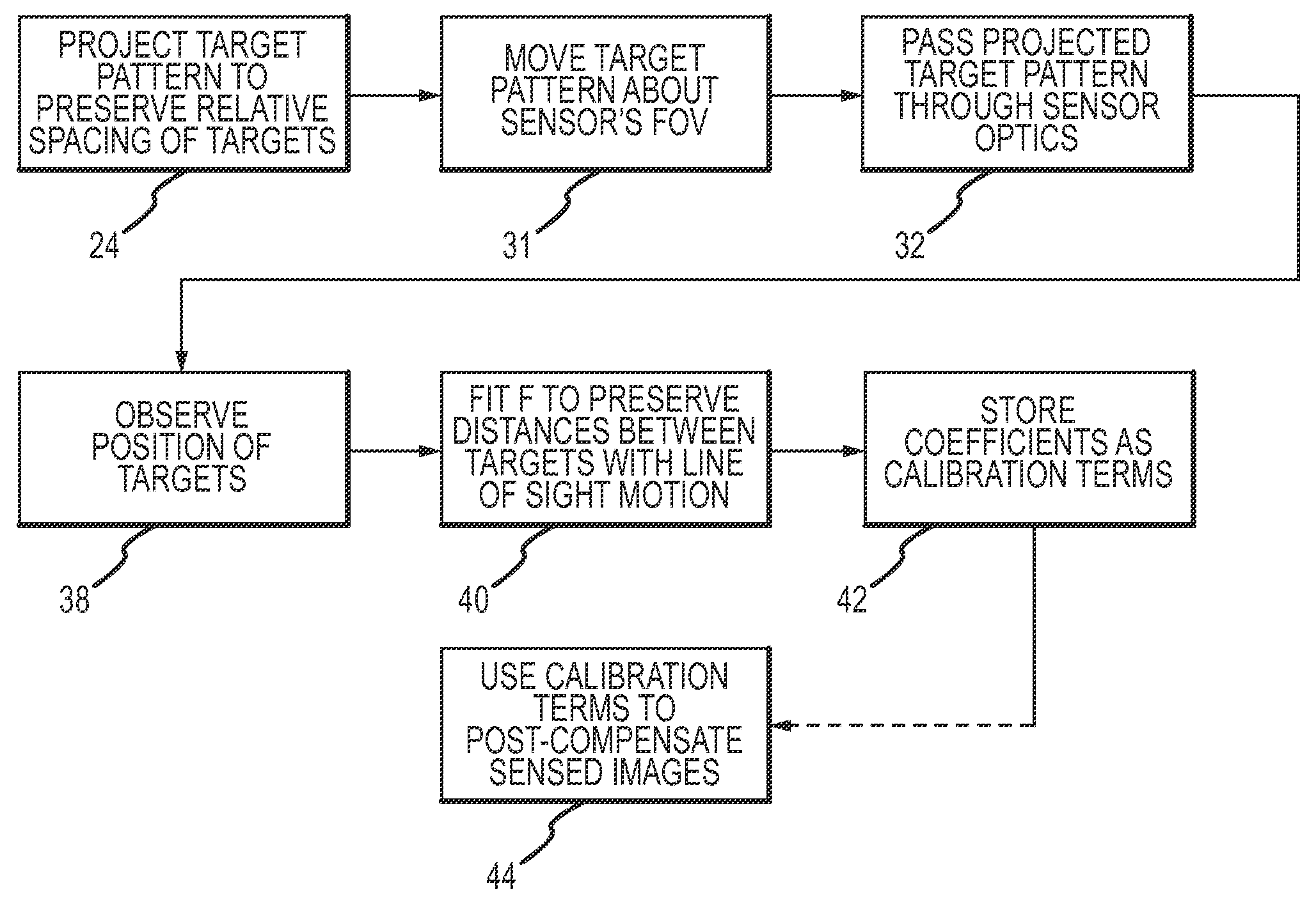
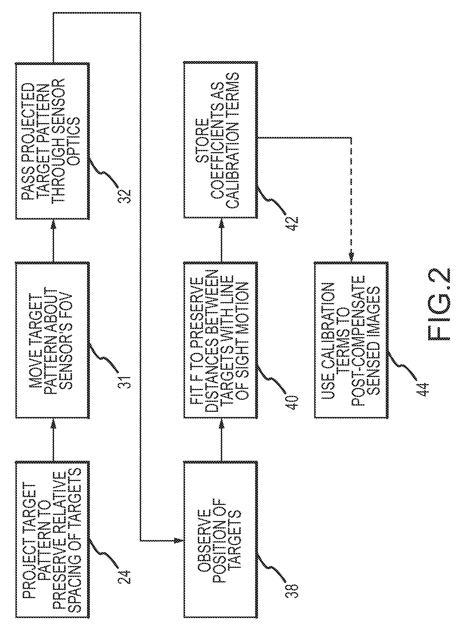
[0022]The present invention provides for performing optical distortion calibration for a flight sensor in a chamber that eliminates calibration of the mirror controller and allows for calibration while the target is in motion across the FOV thus providing a more efficient and accurate calibration.

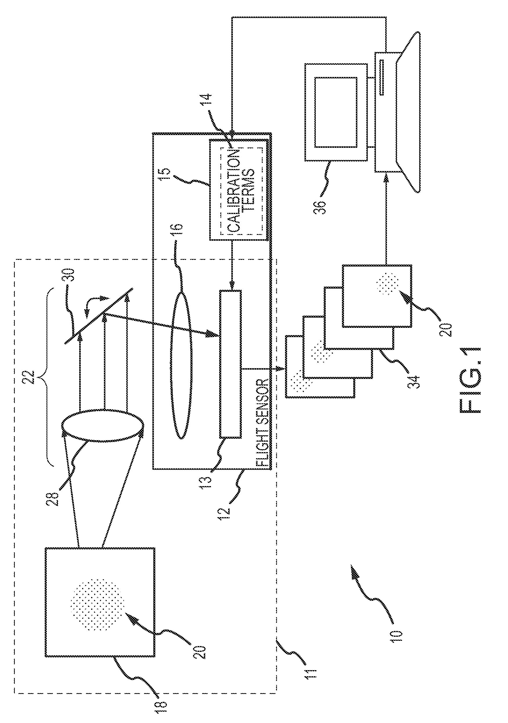
[0023]An exemplary test setup 10 and calibration procedure are illustrated in FIGS. 1 and 2. A vacuum chamber 11 is provided with a flight sensor 12 including an EO sensor 13, calibration terms 14 stored in a tangible medium 15 and sensor optics 16. A target pattern 18 including a plurality of targets 20 is provided in the chamber. An optical system 22 projects the target pattern so that the pattern may be shifted in a field-of-view (FOV) measured by the sensor while preserving the relative positions of the targets. Optical system 22 is suitably configured with a collimating lens 28 that first projects the target pattern into collimated space so that the angular difference position from eac...


PUM


Abstract

Optical distortion calibration for an Electro-Optical sensor in a chamber eliminates calibration of the mirror controller and allows for calibration while the target is in motion across the FOV thus providing a more efficient and accurate calibration. A target pattern is projected through sensor optics with line of sight motion across the sensor FOV to generate a sequence of frames. Knowing that the true distances between the same targets remain constant with line of sight motion across the sensor's FOV, coefficients of a function F representative of the non-linear distortion in the sensor optics are fit from observed target positions in a subset of frames to true line of sight so that distances between targets are preserved as the pattern moves across the FOV. The coefficients are stored as calibration terms with the sensor.

Description

GOVERNMENT LICENSE RIGHTS[0001]The U.S. Government has a paid-up license in this invention and the right in limited circumstances to require the patent owner to license others on reasonable terms as provided for by the terms of Contract HQ0006-01-C-0001 / 101616 awarded by the Ballistic Missile Defense Organization awarded by DARPA-DSO.BACKGROUND OF THE INVENTION[0002]1. Field of the Invention[0003]This invention relates to optical distortion calibration for electro-optical sensors.[0004]2. Description of the Related Art[0005]All imaging systems have some amount of distortion attributable to their optics. Non-linear distortion causes a fixed angular displacement between points in image space to appear to change as the points move across the image. In other words, the observed line-of-sight (LOS) positions are warped. Common types of distortion include pincushion or barrel distortion. Some applications, notably precision stadiometry, require that camera distortions be precisely calibra...

Claims


Application Information

Patent Timeline
Patent Type & Authority Patents(United States)
IPC IPC(8): G01C17/38G01C25/00G01D18/00
CPCG01M11/00G02B27/0025H04N17/002H04N5/3572H04N5/33H04N25/61
Inventor WILLIAMS, DARIN S.WENDT, JODEAN D.
Owner RAYTHEON CO
Why Eureka
Try Eureka