Calibration method and apparatus for panoramic stereo video system

a technology of panoramic stereo and video system, applied in the field of panoramic stereo video system, can solve the problems of conventional methods and algorithms that tend to fail, and achieve the effect of efficiently and accurately calibrating

Active Publication Date: 2020-04-28
SHANGHAI TECH UNIV
View PDF50 Cites 0 Cited by
  • Summary
  • Abstract
  • Description
  • Claims
  • Application Information

AI Technical Summary

Benefits of technology

[0016]In accordance with embodiments of the present invention, the cameras in the camera array can be calibrated efficiently and accurately by simply taking pictures simultaneously at different positions, wherein the cameras are not required to have an overlapping field of view.

Problems solved by technology

Calibrating the extrinsic parameters of these cameras properly is the prerequisite for running any complex vision or video algorithm, as these algorithms will often fail if the spatial relationship between the cameras is not accurately defined.
However, in cases where the overlapping region is small or even does not exist, the conventional methods tend to fail due to low resolution of the overlapping region, or failure to find a common pattern in the overlapping region.

Method used


Image

  • Calibration method and apparatus for panoramic stereo video system
  • Calibration method and apparatus for panoramic stereo video system
  • Calibration method and apparatus for panoramic stereo video system

Examples


Embodiment Construction

[0025]To better illustrate the purpose, technical feature, and advantages of the embodiments of the present invention, various embodiments of the present invention will be further described in conjunction with the accompanying drawings. It is obvious that the draws are but for exemplary embodiments of the present invention, and that a person of ordinary skill in the art may derive additional draws without deviating from the principles of the present invention.

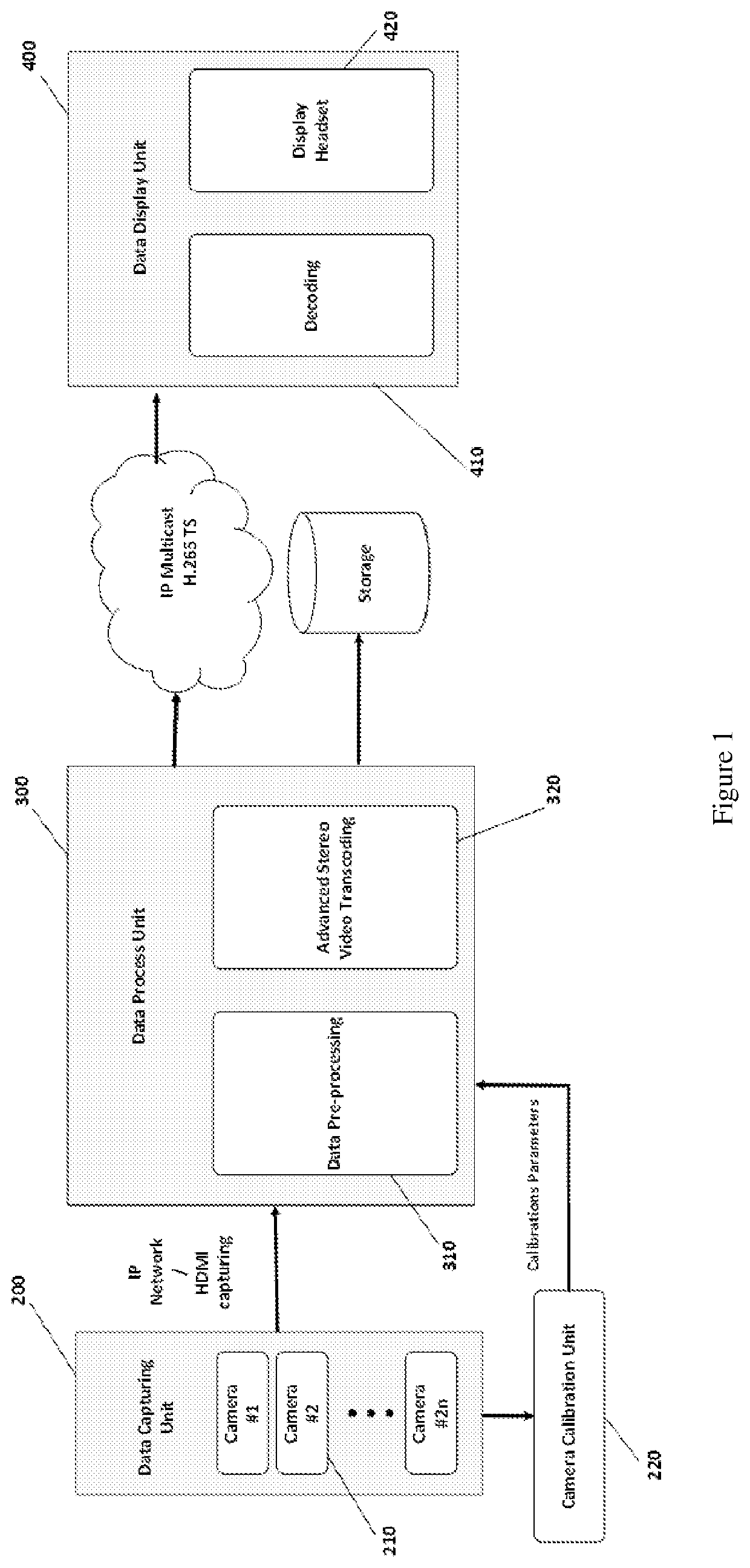
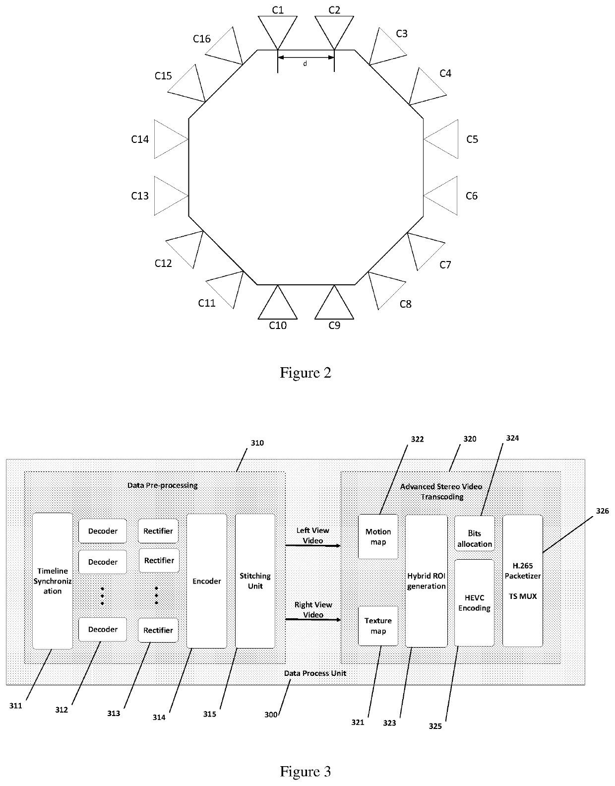
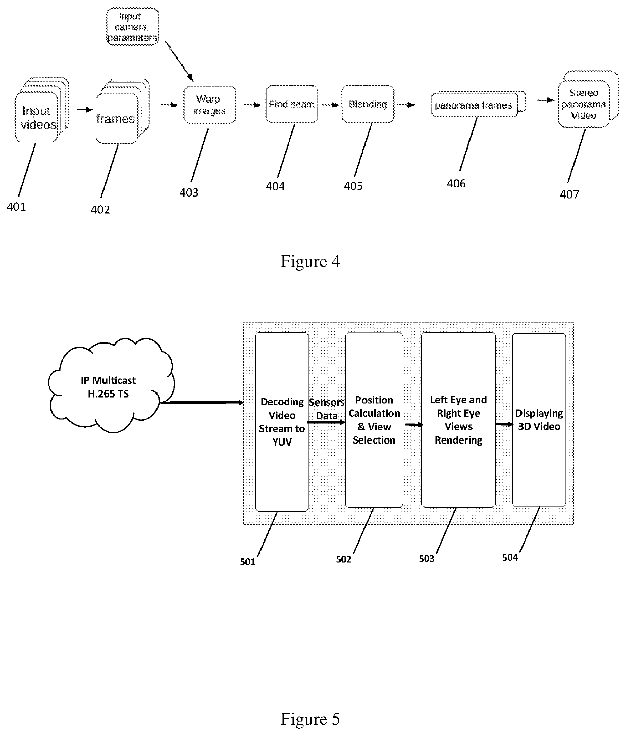
[0026]In accordance with embodiments of the present invention, a panoramic stereo video system including multi-camera video capturing, data processing, stereo video coding, transmission, and 3D displaying is provided. The panoramic stereo video system employs real-time multi-view videos capturing, image rectification and pre-processing, and region of interest (ROI) based stereo video compression. After the transmission and decoding process, a head-mounted display (HMD) headset is used to display the left and right views.

[0027]1...


PUM


Abstract

A method of calibrating a camera array comprising a plurality of cameras configured to capture a plurality of images to generate a panorama, wherein the relative positions among the plurality of cameras are constant, the method comprising: moving the camera array from a first position to a second position; measuring a homogeneous transformation matrix of a reference point on the camera array between the first position and the second position; capturing images at the first position and the second position by a first camera and a second camera on the camera array; and determining a homogenous transformation matrix between the first camera and the second camera based on the images captured by the first camera and the second camera at the first position and the second position. The method further comprises identifying a feature in the images taken by the first camera at the first position and the second position, and estimating a rotation of the first camera from the first position to the second position based on the feature.

Description

CROSS-REFERENCE TO RELATED APPLICATIONS[0001]This application is a National Phase application under 35 U.S.C. § 371 of PCT Application No. PCT / CN2016 / 070712, filed Jan. 12, 2016, the entire contents of which application is hereby incorporated herein by reference.TECHNICAL FIELD[0002]The present invention relates to panoramic stereo video systems for capturing, processing, compressing, and displaying 3D panoramic stereo videos, and more particularly, to methods and apparatus for calibrating camera arrays in the panoramic stereo video systems.BACKGROUND[0003]Multi-camera arrays have been widely used in stereo vision and panoramic video systems. Calibrating the extrinsic parameters of these cameras properly is the prerequisite for running any complex vision or video algorithm, as these algorithms will often fail if the spatial relationship between the cameras is not accurately defined. State-of-the-art camera calibration methods perform well when there is a large overlapping region in ...

Claims


Application Information

Patent Timeline
Patent Type & Authority Patents(United States)
IPC IPC(8): H04N19/126H04N19/523H04N19/176H04N19/159H04N13/282G06T7/33G06T7/80H04N13/239H04N13/243G06T3/40G06T7/73H04N13/246H04N13/106H04N5/232G06T3/00G06K9/62H04N13/128H04N13/00
CPCH04N13/128H04N19/126H04N19/176H04N19/159G06T7/85G06T7/74G06T3/40G06T3/0093H04N13/246H04N13/282G06T3/4038H04N5/23238H04N13/243H04N13/106G06K9/6202H04N19/523H04N13/239G06T7/337G06T2207/10021H04N2013/0081H04N19/17H04N19/124H04N19/139H04N19/14H04N19/597H04N23/698
Inventor YU, JINGYIMA, YI
Owner SHANGHAI TECH UNIV
Why Eureka
Try Eureka