Radar altimeter

Active Publication Date: 2006-03-02
HONEYWELL INT INC
View PDF14 Cites 40 Cited by
  • Summary
  • Abstract
  • Description
  • Claims
  • Application Information

AI Technical Summary

Benefits of technology

[0018] In accordance with yet another aspect of the invention, a constant modulation period causes changes in altitude to result in a linear change in the difference frequency of an FM/CW receiver. The invention provides a 6 dB per octave high pass filter in the receiver such that the amplitude of a given radar cross-section reflection remains constant as a function of altitude. The high pass filter eliminates the need for automatic gain control and provides a means to instantly compensate for signal amplitude variation as function of altitude. The invention includes an analog to digital converter with a sufficient number of bits to account for the variation in the amplitude of the reflected signal caused by a wide range of reflectivity of the ground.
[0019] In

Problems solved by technology

Similarly, microwave sources used in present radar altimeters used open loop methods because microwave devices did not exist to permit closed phase lock loops.
At low altitudes, conventional dual antenna altimeters may erroneously acquire reflections from aircraft components such as engines and wheel gear instead of the correct ground reflection.
However, temperature and moisture affect coax cables by increasing insertion loss, increasing reflection coefficients and changes in propagation delay time.
Therefore, no means exists to continuously calibrate the true electrical length of the connecting cable.
Maloratski also presents closed loop analog circuitry for continuously adjusting modulation rate in order to produce a constant frequency received signal but the loop does not control the linearity or phase noise of the radar modulation.
Maloratski's closed loop analog circuitry provides no means to verify that the modulation function is nearly ideally linear as a function of time, temperature or other environmen

Method used


Image

  • Radar altimeter
  • Radar altimeter
  • Radar altimeter

Examples


Embodiment Construction

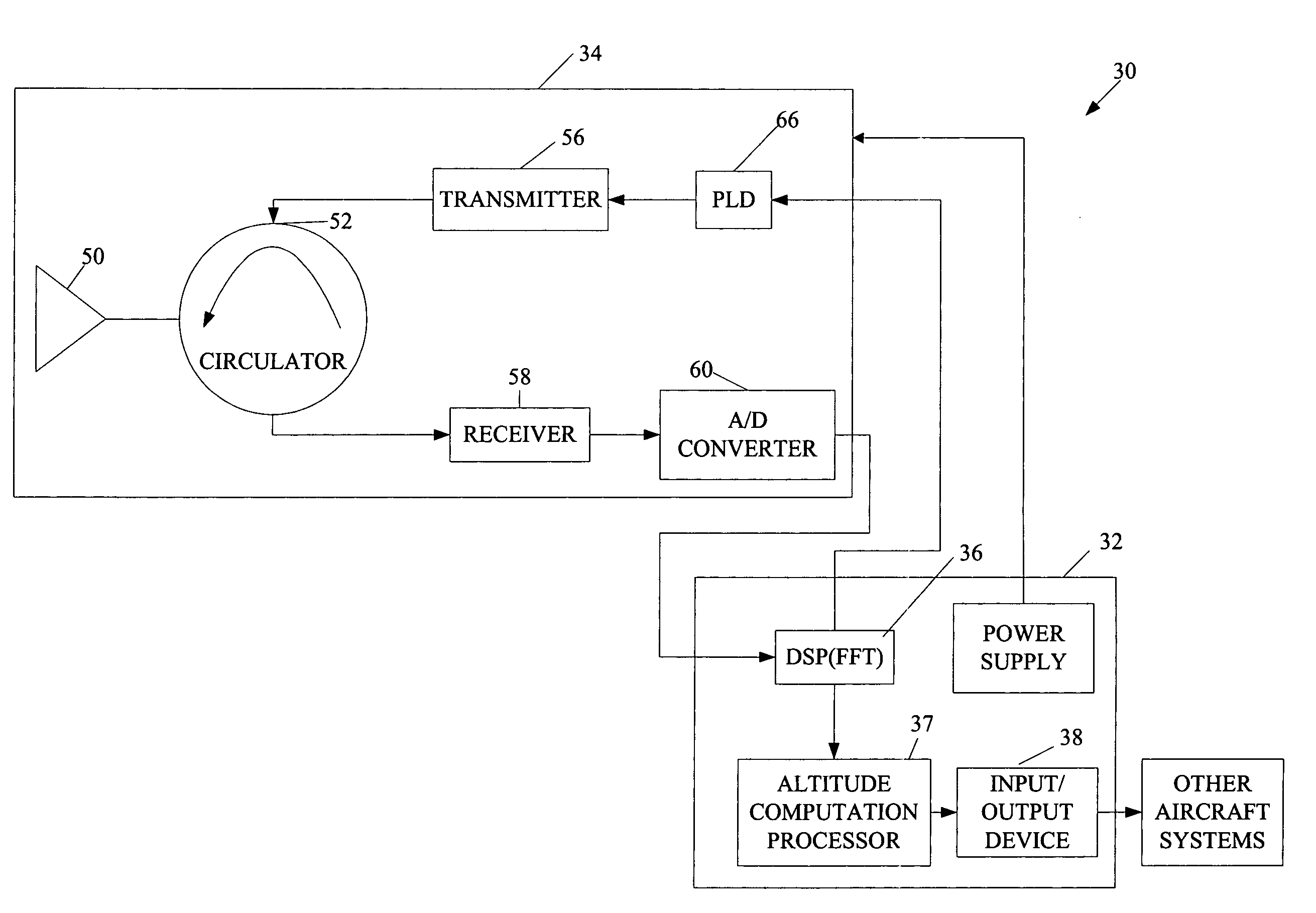
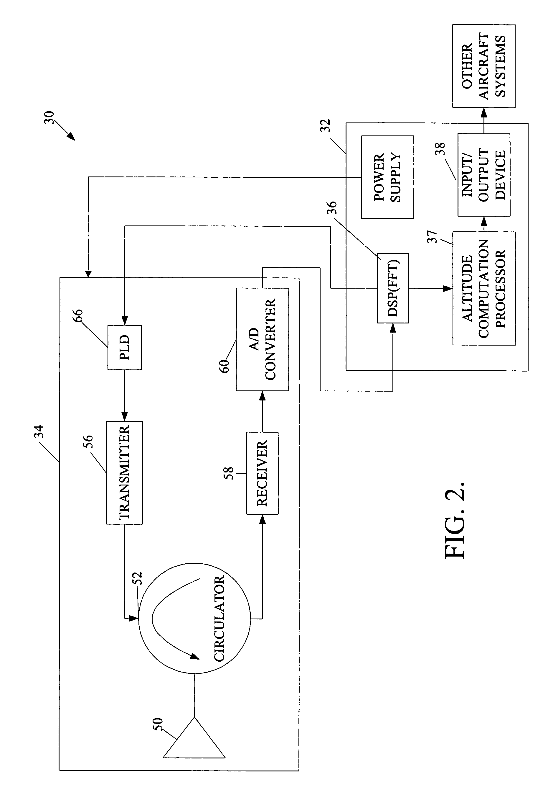
[0027]FIG. 2 illustrates a system 30 that provides more accurate radar altimeter measurements and tail strike warnings. The system 30 includes a radar altimeter 34 and an signal processing system 32. The signal processing system 32 includes a processor 36, an Altitude Computation Processor (ACP) 37 and an input / output device 38. In one embodiment, the processor 36 is a digital signal processor (DSP) with Fast Fourier Transform (FFT) or a Field Programmable Gate Array (FPGA). The radar altimeter 34 is in signal communication with the signal processing system 32 and other aircraft systems, such as a ground-proximity warning system. The radar altimeter 34 sends serial data produced by an Analog to Digital (A / D) Converter 60 to the processor 36, which in turn transfers altitude bin data to the ACP 37. The ACP 37 analyzes distance to ground values and may generate a tail strike warning based on the analysis. If the ACP 37 produces a tail strike warning, the input / output device 38 present...


PUM


Abstract

The present invention provides a radar altimeter system with a closed loop modulation for generating more accurate radar altimeter values. The system includes an antenna, a circulator, a receiver, and a transmitter. The circulator receives or sends a radar signal from/to the antenna. The receiver receives the received radar signal via the circulator. The transmitter generates a radar signal and includes a phase-locked loop circuit for generating the radar signal based on a pre-defined phase signal. The transmitter includes a direct digital synthesizer that generates the phase signal based on a pre-defined clock signal and a control signal. The system includes a digital signal processor and a tail strike warning processor that determine position of a tail of the aircraft relative to ground and present an alert if a warning condition exists based on the determined position of the tail of the aircraft and a predefined threshold.

Description

FIELD OF THE INVENTION [0001] This invention relates to radar altimeters. BACKGROUND OF THE INVENTION [0002] Typical aircraft radar altimeters include a separate receiving antenna and transmission antennas located on the bottom of the fuselage of commercial or private aircraft. Separate transmit and receive antennas have historically been used in order to provide isolation between the transmitter and receiver during continuous transmission and reception of a radar signal. Transmitter to receiver isolation was required because of technology shortcomings of microwave signal sources and microwave device packaging technology. Similarly, microwave sources used in present radar altimeters used open loop methods because microwave devices did not exist to permit closed phase lock loops. Technology now readily available permits exceptionally low phase noise signals with exceptionally high quality linear frequency modulation under virtually any load or environmental conditions. [0003] Operati...

Claims


Application Information

Patent Timeline
IPC IPC(8): G01S13/08G01S7/40
CPCG01S7/032G01S13/882G01S7/35G01S7/038G01S7/034
Inventor VACANTI, DAVID C.
Owner HONEYWELL INT INC
Why Eureka
Try Eureka