
Apparatus and method for determining signal quality in a geolocation system

a geolocation system and signal quality technology, applied in direction finders, direction finders using radio waves, instruments, etc., can solve the problems of reducing the accuracy of the target's determined location, and it is not possible to determine a precise location for a target uni

Active Publication Date: 2010-05-20
DRS SIGNAL SOLUTIONS
View PDF10 Cites 7 Cited by
  • Summary
  • Abstract
  • Description
  • Claims
  • Application Information

AI Technical Summary

Benefits of technology

[0012]Known statistical techniques provide an equation that defines how the variance is affected by various signal parameters, including the signal bandwidth, the signal to noise ratio and the signal duration. The equation is referred to as the Cramer-Rao lower bound for the variance of the estimate. This equation states that the variance of the estimate is inversely proportional to the cube of the bandwidth, the square of the joint signal to noise ratio and the coherent integration interval (i.e., the time span of the observed signal). Obviously, the bandwidth of the received signal has the greatest impact on the variance of the time difference estimate and therefore on the accuracy of the geolocation solution.
[0017]The inventors have determined that a bandwidth of about 15 kHz, about 0.5 seconds of stare (i.e., time span of the observed signal) and an SNR of about 15 dB provides a reasonable location accuracy.
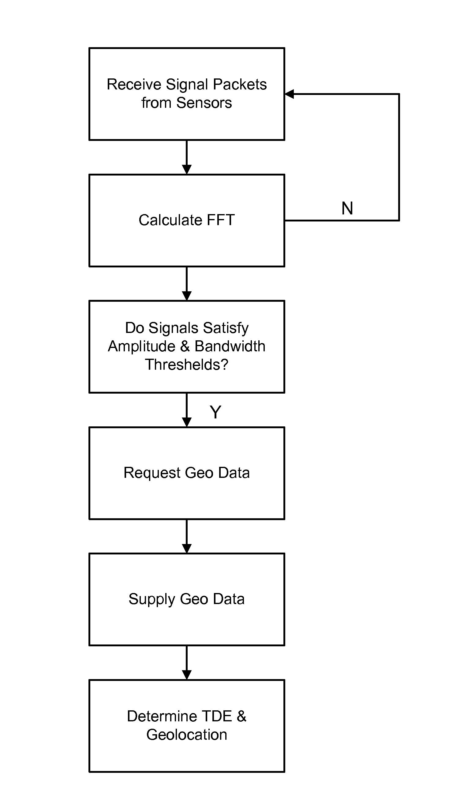
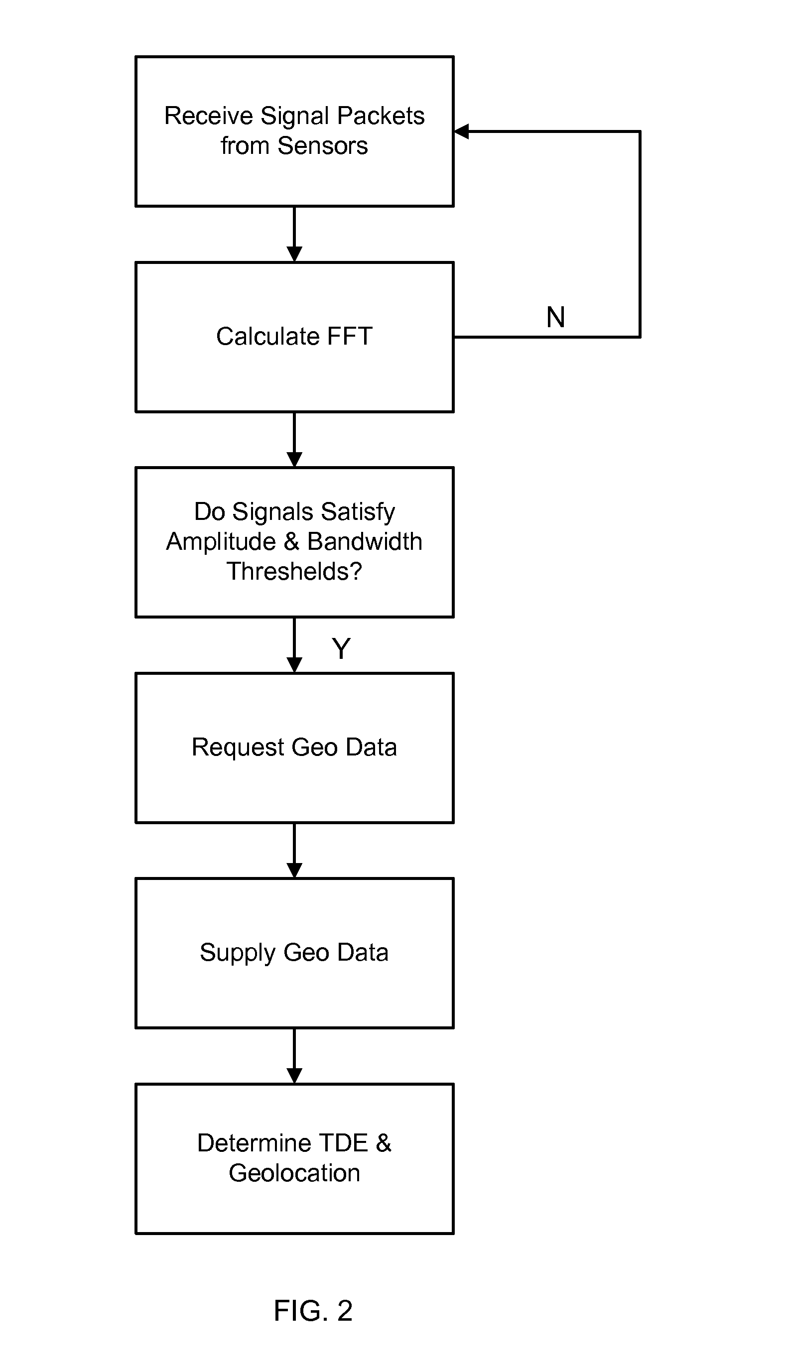
[0019]For example, to minimize the variance in the time difference estimate it may be necessary to require that all sensor signals satisfy the amplitude and bandwidth thresholds. This technique reduces the stress on the system's communications infrastructure by transferring only data that will meaningfully contribute to the geolocation processing. The technique also improves the accuracy of the geolocation solutions by providing only signal data with adequate bandwidth and amplitude for meaningful geolocation processing.
[0021]This technique reduces the load on the communications infrastructure while providing more meaningful data to the geolocation algorithms, resulting in more accurate and faster location solutions.

Problems solved by technology

With only two receiving stations using a TDOA method, it is generally not possible to determine a precise location for a target unit, but rather only a locus of points along a curve.
The target signal necessarily takes different paths to each sensor and may be corrupted by noise and interference as it propagates.
Such noise and interference can reduce the accuracy of the target's determined location.
Thus determination of the time difference of arrival of the signal at any two sensors is a problem in statistical estimation and therefore the time difference estimate (TDE) is described by both a mean and a variance.

Method used


Image

  • Apparatus and method for determining signal quality in a geolocation system
  • Apparatus and method for determining signal quality in a geolocation system
  • Apparatus and method for determining signal quality in a geolocation system

Examples


Embodiment Construction

[0010]Before describing in detail the particular apparatuses and methods for determining modulation quality of a signal, in accordance with the various embodiments of the present invention, it should be observed that these embodiments reside primarily in a novel combination of hardware and software elements related to the claimed apparatuses and methods. Accordingly, the hardware and software elements have been represented by conventional elements in the drawings, showing only those specific details that are pertinent to the presented embodiments, so as not to obscure the disclosure with details that will be readily apparent to those skilled in the art having the benefit of the description herein.

[0011]The following embodiments are not intended to define limits as to the structures or methods of the invention but only to provide exemplary constructions. The embodiments are permissive rather than mandatory and illustrative rather than exhaustive.

[0012]Known statistical techniques pro...


PUM


Abstract

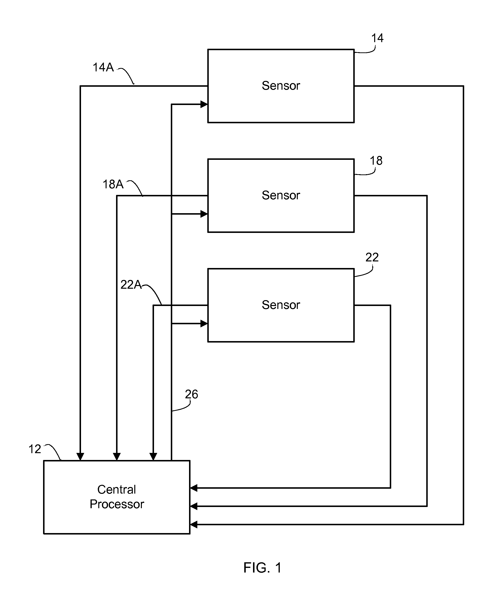
In a geolocation system for determining a geolocation of a target emitter, a method for determining the geolocation. The method comprises receiving a signal transmitted from the target emitter at each one of a plurality of sensors; determining whether signals received at n sensors, from among the plurality of sensors, satisfy one or more threshold values related to a condition of the received signals; if signals received at n sensors satisfy the threshold value, commanding m of the n sensors to transmit the signal received thereat or information related to the signal received thereat to a processor; at the processor, determining time difference estimates for the m received signals and determining the geolocation of the target emitter from the time difference estimates.

Description

CLAIM OF PRIORITY[0001]This application claims priority under 35 U.S.C. section 119(e) to U.S. Provisional Patent Application assigned application No. 61 / 091,463, entitled Apparatus and Method for Determining Modulation Quality in a Geolocation System and filed on Aug. 25, 2008, the entire contents of which are hereby incorporated by reference.FIELD OF THE INVENTION[0002]This invention relates to an apparatus and method for determining modulation quality of a signal, in particular a signal employed to determine a location of an emitter.BACKGROUND OF THE INVENTION[0003]In a time difference of arrival geolocation system the signal from a target emitter is received at three or more geographically distributed sensors. To determine a location of the emitter, it is necessary to calculate the difference in the arrival time of the same signal at each receiving sensor. These time differences (also referred to as the time difference of arrival or TDOA) correspond to differences in distance be...

Claims


Application Information

Patent Timeline
IPC IPC(8): G01S3/02
CPCG01S5/06G01S5/021
Inventor REYNOLDS, TIMMCLEOD, SHANERUSSELL, JAMES
Owner DRS SIGNAL SOLUTIONS
Learn More