Method and device for a proactive cooling system for a motor vehicle

a technology for motor vehicles and cooling systems, applied in the direction of engine cooling apparatus, liquid cooling, machines/engines, etc., can solve the problems of poor cooling system response, poor cooling temperature control, and large heat generation of the internal combustion engine of a motor vehicle during use, so as to improve the cooling of the motor vehicle. , the effect of improving the cooling of the motor vehicl

Inactive Publication Date: 2009-05-19
INT TRUCK INTPROP LLC
View PDF16 Cites 16 Cited by
  • Summary
  • Abstract
  • Description
  • Claims
  • Application Information

AI Technical Summary

Benefits of technology

[0013]According to the invention, there is provided a proactive cooling system to improve the cooling of a motor vehicle apparatus, such as an engine or transmission, in a motor vehicle and a method therefor. The proactive cooling system includes a primary cooling system connected to the motor vehicle apparatus, an electronic controller, an information collecting module cooperating with the electronic controller and an auxiliary cooling system.

Problems solved by technology

The internal combustion engine of a motor vehicle generates large quantities of heat during use.
Motor vehicles powered by large engines, however, typically require a liquid cooling system.
The cooling system thus suffers from poor response when controlling the coolant temperature to the target coolant temperature.
In particular, when a quantity of heat equivalent to a cooling loss of the engine changes with a change in the operating state of the engine, coolant temperature control is poor.
If the coolant loss changes as described above, a power loss occurs which is detrimental to improvements in the fuel efficiency and the output performance.
A similar problem may be encountered in a cooling system in which the flow rate of coolant passing through a radiator is controlled by an water pump, in place of the flow control valve.

Method used


Image

  • Method and device for a proactive cooling system for a motor vehicle
  • Method and device for a proactive cooling system for a motor vehicle
  • Method and device for a proactive cooling system for a motor vehicle

Examples


Embodiment Construction

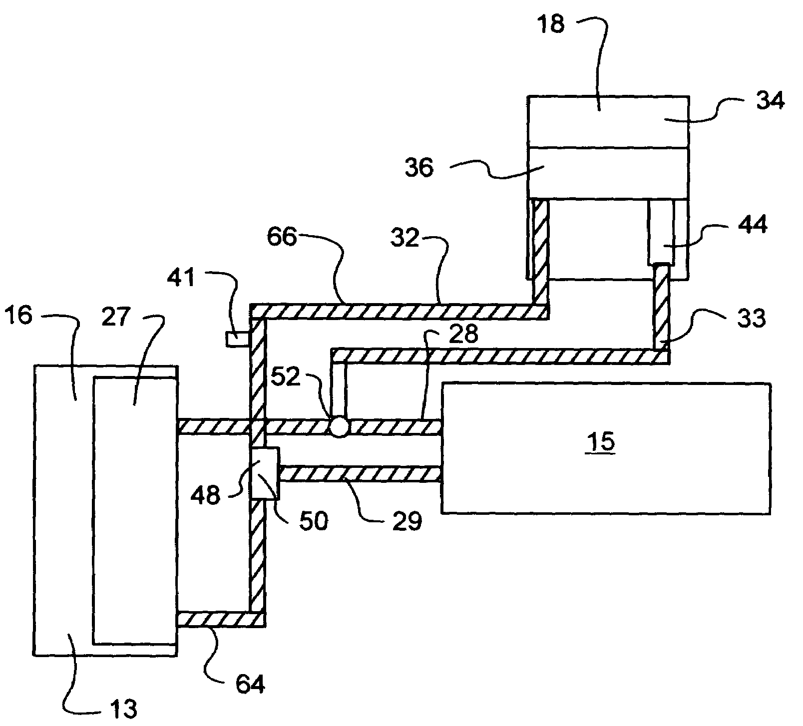
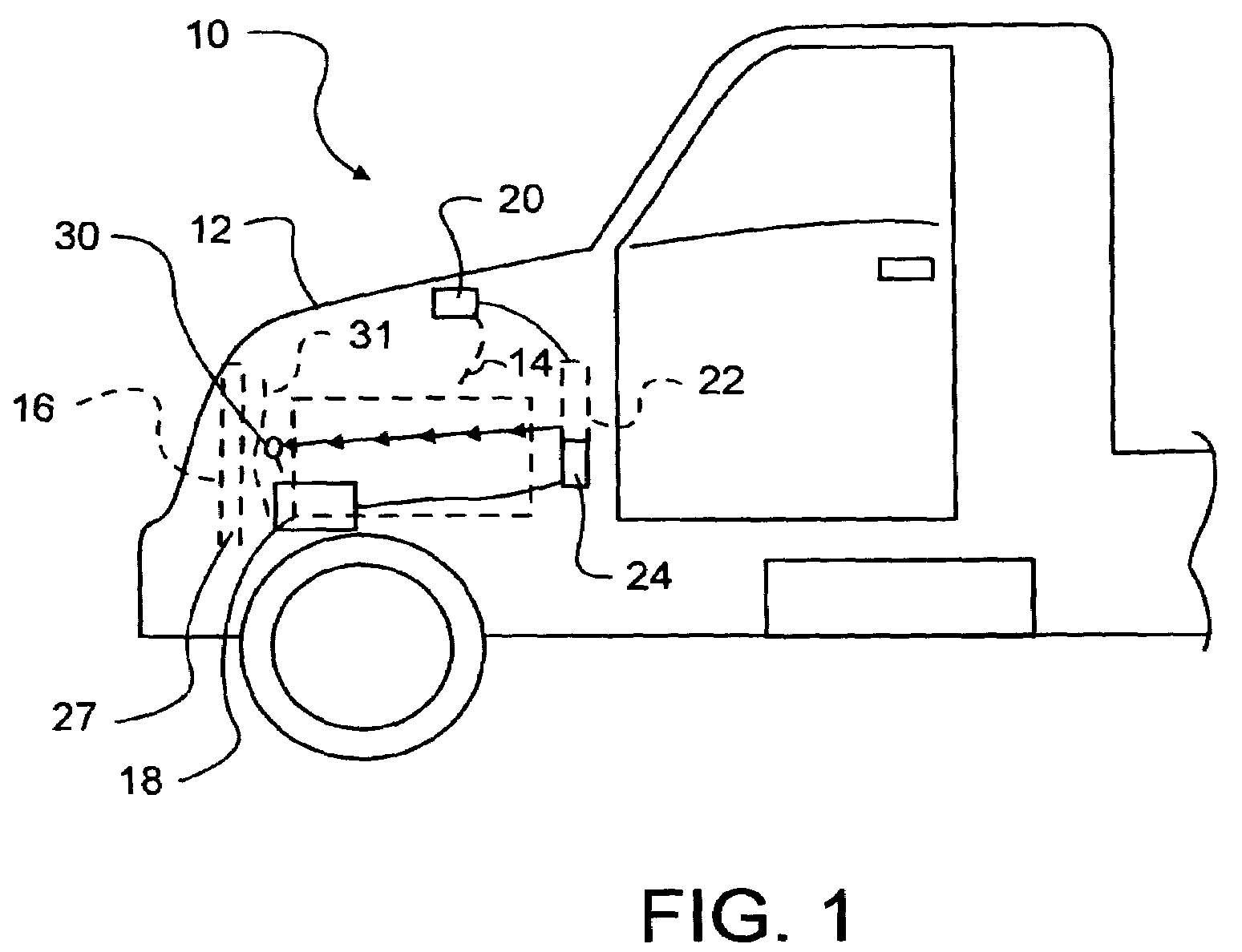
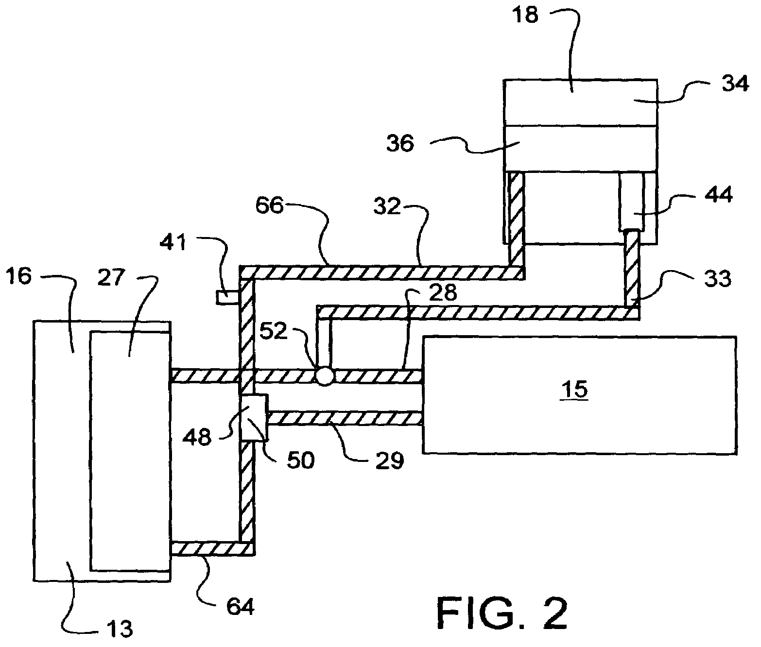
[0028]Turning to the figures where like reference numerals refer to like structures, FIG. 1 shows a front portion of a motor vehicle 10, such as a truck 11, having an engine compartment 12 that houses an engine 14. The engine is coupled through a drivetrain to drive wheels (not shown) for moving the truck when driven. Engine 14 is shown by way of example as a diesel engine having its own liquid cooling system. Coolant circulates through coolant passages in the block and heads of engine 14 that form the engine combustion chambers. A primary pump 30 is typically used to circulate the coolant.

[0029]Some of the heat of combustion created in the engine combustion chambers radiates to the coolant circulating in a primary circuit 64 in the primary cooling system 13. The primary cooling system 13 has coolant circulating through a primary circuit 64 between a primary heat exchanger 16, such as radiator 27, and a heated motor vehicle apparatus 15, such as the engine 14 or the transmission 26....


PUM


Abstract

A proactive cooling system and method improve the cooling of a motor vehicle apparatus, such as an engine or transmission, in a motor vehicle. The proactive cooling system boosts the primary cooling system connected to the motor vehicle apparatus by using an electronic controller, an information collecting module for collecting information related to the operation of the motor vehicle and an auxiliary cooling system. The auxiliary cooling system uses a power supply and a secondary cooling system in fluid communication with the primary cooling system. The power supply turns on the secondary cooling system by activating an activator and a secondary pump. The activator opens a bypass circuit to divert coolant from the primary cooling system into the secondary cooling system where the diverted coolant is cooled in a secondary heat exchanger. A secondary pump circulates the coolant through the bypass circuit and back to the primary cooling system.

Description

BACKGROUND OF THE INVENTION[0001]1. Field of the Invention[0002]The present invention relates to cooling systems for motor vehicles powered by engines, such as trucks that are powered by internal combustion engines.[0003]2. Description of the Prior Art[0004]The internal combustion engine of a motor vehicle generates large quantities of heat during use. Air-cooled or liquid-cooled cooling systems remove the generated heat from the engine and other components of a motor vehicle. Air-cooling, where heat transfer occurs directly from the engine to ambient air, may be adequate for some small engines. Motor vehicles powered by large engines, however, typically require a liquid cooling system.[0005]One such liquid cooling system uses a radiator in a coolant circuit with the engine for cooling a coolant or cooling water, and a water pump or a flow control valve to control the flow rate of the coolant that passes through the radiator. A flow control valve typically opens in response to a con...

Claims


Application Information

Patent Timeline
Patent Type & Authority Patents(United States)
IPC IPC(8): F01P3/00F01P7/00
CPCF01P7/165F01P7/167F01P2005/125F01P2023/08
Inventor BRADLEY, JAMES C.WOOLDRIDGE, SCOTT A.KLINGER, RODNEY J.
Owner INT TRUCK INTPROP LLC
Why Eureka
Try Eureka