Distance measurement device and distance measurement method

a technology of distance measurement and distance measurement method, which is applied in the direction of distance measurement, instruments, surveying and navigation, etc., can solve the problems of lowering the accuracy of measurement of affecting the accuracy of measurement, and taking a significant long time for measuring the distance to the object, so as to achieve high accuracy of measurement

Inactive Publication Date: 2009-05-19
NAGOYA UNIVERSITY
View PDF11 Cites 50 Cited by
  • Summary
  • Abstract
  • Description
  • Claims
  • Application Information

AI Technical Summary

Benefits of technology

[0006]As described above, the prior art distance measurement method captures images of an object in different shooting directions, processes the captured images of the object, and computes the distance to the object based on the processed images. This takes a significantly long time for measurement of the distance to the object. The image processing and the computation may be simplified to shorten the total time required for the measurement. The simplified image processing and computation, however, undesirably lowers the measurement accuracy. This prior art method also requires regulation of the shooting positions of the object. The inadequate regulation may lower the accuracy of measurement of the distance to the object.
[0007]The distance measurement device and the distance measurement method of the invention thus aim to enable high-speed measurement of a distance to an object. The distance measurement device and the distance measurement method of the invention also aim to enable highly-accurate measurement of a distance to an object.

Problems solved by technology

This takes a significantly long time for measurement of the distance to the object.
The simplified image processing and computation, however, undesirably lowers the measurement accuracy.
The inadequate regulation may lower the accuracy of measurement of the distance to the object.

Method used


Image

  • Distance measurement device and distance measurement method
  • Distance measurement device and distance measurement method
  • Distance measurement device and distance measurement method

Examples


second embodiment

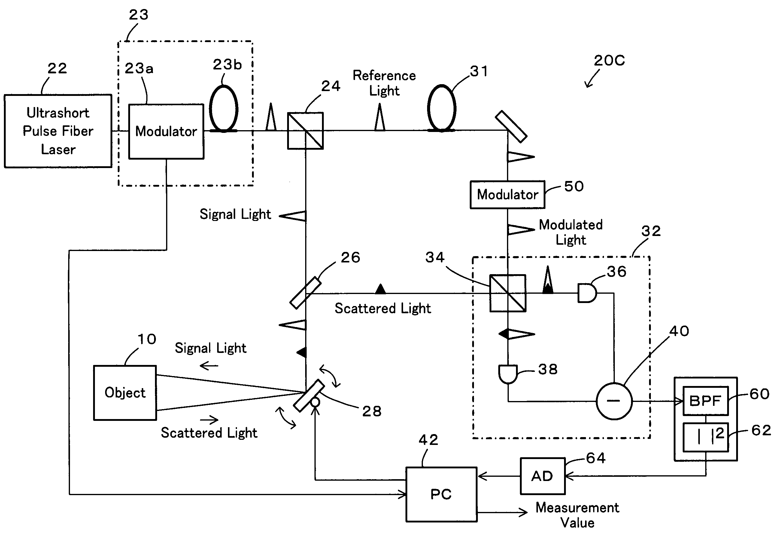
[0042]In the distance measurement device 20B of the second embodiment, the wavelength change unit 23 includes a modulator 23a that modulates the intensity of the pulsed light from the ultrashort pulse fiber laser 22 and a variable wavelength optical fiber 23b that varies the wavelength of the pulsed light according to the intensity of the pulsed light. The modulator 23a adopted in this embodiment is an acousto-optical modulator having a transmission rate of not lower than 75% in a modulation bandwidth of 1.8 MHz. The modulator 23a is adjusted to modulate the intensity of the pulsed light and generate sawtooth wave having a period of 10 kHz. The modulated intensity of the pulsed light is output as an adjustment value of the wavelength of the pulsed light to the computer 42. The graph of FIG. 4 shows a variation in intensity of the pulsed light modulated by the modulator 23a against time. The modulator 23a is not restricted to the acousto-optical modulator of the above performance but...

third embodiment

[0053]The modulator 50 adopted in the distance measurement device 20C of the third embodiment is the acousto-optical modulator that shifts the reference light A to the 27 MHz band. The shifted frequency band is, however, not restricted to the 27 MHz band. The modulator 50 may be any acousto-optical modulator that shifts the reference light A to any suitable frequency band. In this case, the band-pass filter 60 is selected corresponding to the shifted frequency band. The modulator 50 is not limited to the acousto-optical modulator but may be another modulator, for example, an electro-optical modulator. A modulator with the capability of varying the shifted frequency band is especially preferable. Appropriate regulation of the shifted frequency band enables three-dimensional measurement with higher accuracy.

[0054]The distance measurement device 20C of the third embodiment has the modulator 50, the band-pass filter 60, the square law detector 62, and the A-D converter 64 in addition to...


PUM


Abstract

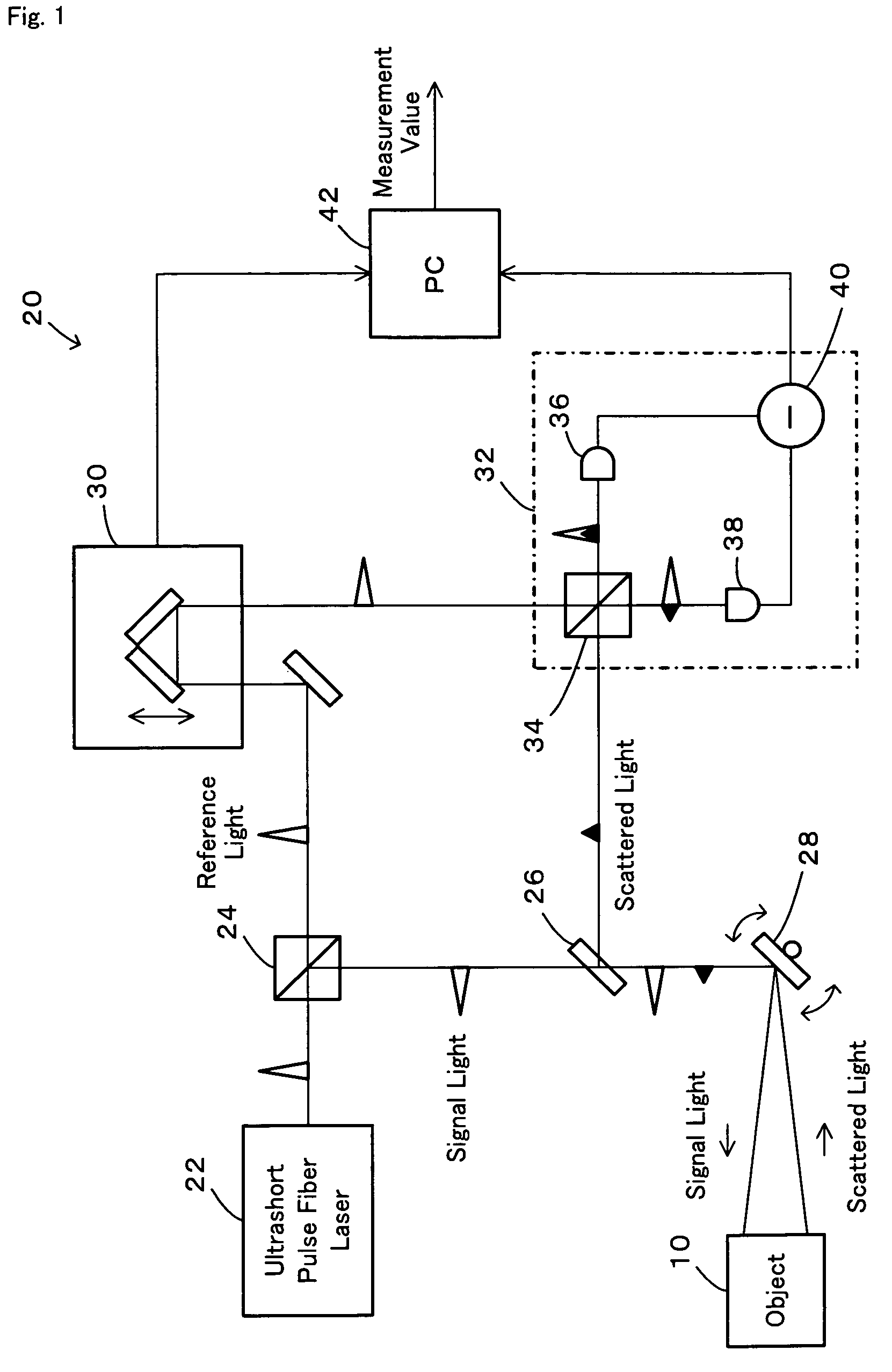
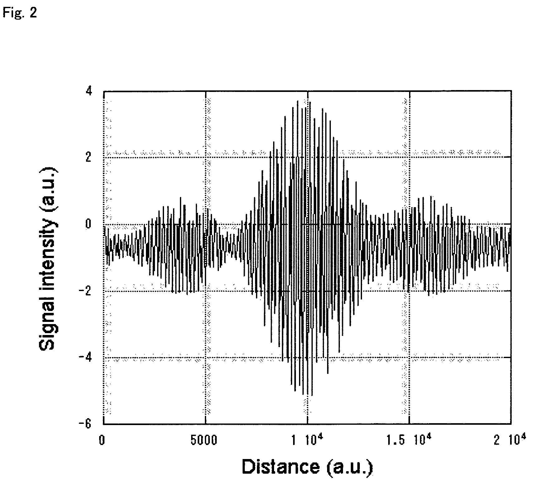
A distance measurement device that provides high speed and accuracy. A light divider separates pulsed light emitted from an ultrashort pulse fiber laser into reference light A and signal light. A scanning mirror unit irradiates an object with the signal light and receives scattered light B, which is reflected from the object. An optical path length adjustment unit adjusts an optical path length of the reference light A. A differential detector detects the degree of interference of the reference light A having the adjusted optical path length with the scattered light B and outputs the detected degree of interference as an interference signal. A computer specifies an adjustment value, set in the optical path length adjustment unit, to attain a specific optical path length maximizing the interference signal and uses the specified adjustment value to compute the distance from the scanning mirror unit to the object.

Description

BACKGROUND OF THE INVENTION[0001]1. Field of the Invention[0002]The present invention relates to a distance measurement device and a distance measurement method. More specifically the invention pertains to a distance measurement device that measures a distance to an object and a corresponding distance measurement method.[0003]2. Description of the Prior Art[0004]A conventional distance measurement method adopts an image processing technique to measure the distance to an object. This technique captures images of an object in two different shooting directions and processes the captured images of the object in the different shooting directions and computes a distance from a reference position to the surface of the object, based on the processed images.[0005]A proposed technique relating to intense pulsed light varies the wavelength of the pulsed light according to the intensity of the pulsed light (see, for example, Japanese Patent No. 3390755). This technique utilizes the characterist...

Claims


Application Information

Patent Timeline
Patent Type & Authority Patents(United States)
IPC IPC(8): G01C3/08G01S17/10G01S7/4865
CPCG01S7/4818G01S7/484G01S7/487G01S17/10G01S7/4865G01S7/4817
Inventor NISHIZAWA, NORIHIKOGOTO, TOSHIO
Owner NAGOYA UNIVERSITY
Why Eureka
Try Eureka