Plasma-assisted disinfection of milking machines

a technology of milking machine and plasma, which is applied in the field of cleaning and sanitizing the teat cup liners of milking machines, can solve the problems of devastation of milking machine production, death of cows, and rapid spread of mastitis outbreaks in herds, and achieves the effect of convenient implementation

Inactive Publication Date: 2009-05-26
WISCONSIN ALUMNI RES FOUND
View PDF23 Cites 82 Cited by
  • Summary
  • Abstract
  • Description
  • Claims
  • Application Information

AI Technical Summary

Benefits of technology

[0013]Thus, after the milking machine is used to milk a cow, it may be disinfected by removing the cow's teat from the teat cup shell 102 and its liner 114, inserting the second electrode 208 within the liner 114, and activating the power supply 222 to cause plasma generation about the liner's interior surface 122 to disinfect it. After sufficient time has passed for a desired degree of disinfection to occur, the second electrode 208 may be removed from the liner 114, and the milking machine may proceed for use on the next cow within the herd. The arrangement does not require significant time for disinfection, nor does it require the use of chemicals or other consumables. Additionally, it is easily implemented within the structures of conventional milking machines, particularly if the first electrode 202 serves as a ground electrode (in which case it does not bear a charge, and thus little or no wiring is required on the teat cup shell 102). In milking machines which rely on pneumatic stimulation of the teat, the first electrode may be formed in sections 204 (e.g., windings) with apertures or spaces 206 defined therebetween so that any pumping pressure supplied by the pressure supply 112 can be communicated through the first electrode 202 to the liner 114 to cause it to radially flex.
[0014]In another possible arrangement (which is not depicted in the accompanying drawings), the first electrode 202 may be formed on or within the teat cup liner 114 itself, as by forming the first electrode 202 as a metallic layer on the liner's exterior surface 126, and / or by forming the first electrode 202 as a conductive network within the body of the teat cup liner 114. In these arrangements, the first electrode 202 is preferably flexible so that it will not hinder the flexure of the teat cup liner 114.

Problems solved by technology

A mild case of mastitis in a cow can merely reduce milk production, while in a severe case, it may result in the death of the cow.
Thus, a mastitis outbreak can rapidly spread through a herd and devastate its milk production.
However, since milking machines are rarely cleaned between milking individual cows, mastitis-causing organisms can be easily transferred between cows during a milking session.
These have not been widely adopted because they are expensive to install and maintain, and they require large amounts of water and disinfectants for operation.
Additionally, they are not always effective in removing bacteria populations from the teat cup liner 114.

Method used


Image

  • Plasma-assisted disinfection of milking machines
  • Plasma-assisted disinfection of milking machines

Examples


Embodiment Construction

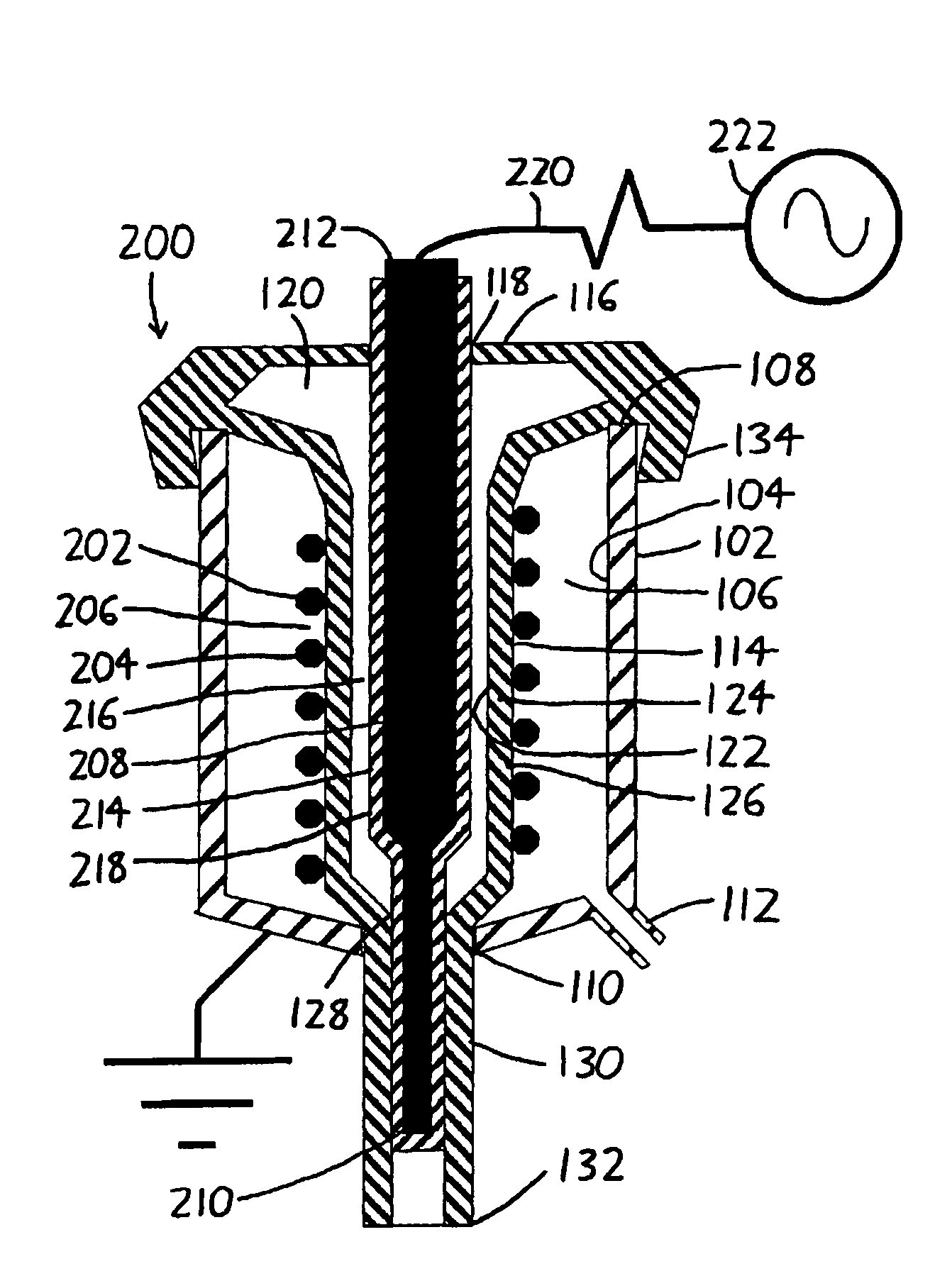
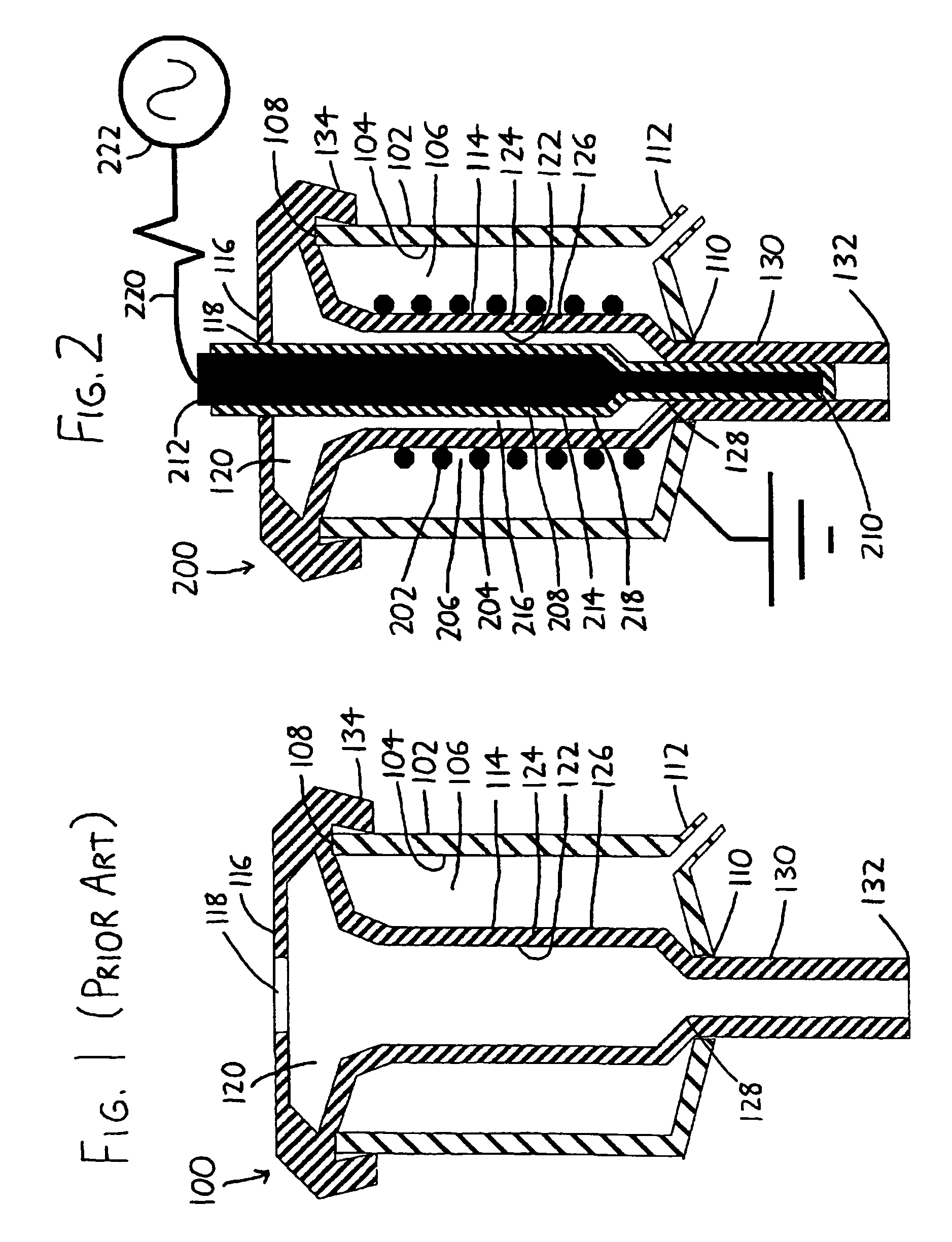
[0018]Referring to FIG. 2, wherein the teat cup 200 is modified from the teat cup 100 of FIG. 1 to present an exemplary version of the invention, a conductive first electrode 202 is situated within the teat cup shell 102, and is configured to closely surround the teat cup liner's exterior surface 126 (more specifically, to surround at least a portion of the exterior surface 126 of the liner barrel 124) as the teat cup liner 114 extends from the teat cup mouth 108 to its extraction end 110. The first electrode 202 is depicted as a coil wound about the exterior surface 126, though it could take other forms, such as a continuous conducting shell surrounding the liner's exterior surface 126. However, since it is desirable to have at least a portion of the liner's exterior surface 126 exposed to the pulsation chamber 106 so that pressure pulses supplied to the pulsation chamber 106 from the pressure supply 112 will flex the liner barrel 124 to massage the teat, a coiled first electrode 2...


PUM


Abstract

In a milking machine teat cup wherein an animal to be milked has its teat inserted into a teat cup liner during milking, a first electrode extends about or within at least a portion of the teat cup liner. To clean and / or disinfect the liner, a second electrode is inserted into the liner and the two electrodes are charged so as to generate plasma in any free space between the inserted second electrode and the interior surface of the liner. The generated plasma species destroy organisms that cause mastitis, and can additionally kill other unwanted organisms and / or perform cleaning of the liner's interior.

Description

STATEMENT REGARDING FEDERALLY SPONSORED RESEARCH[0001]This invention was made with United States government support awarded by the following agencies:[0002]USDA / CSREES Grant No(s).:2004-35201-14121The United States has certain rights in this invention.FIELD OF THE INVENTION[0003]This document concerns an invention relating generally to milking machines, and more specifically to methods and apparata for cleaning and sanitizing milking machine teat cup liners.BACKGROUND OF THE INVENTION[0004]A cross-sectional view of a milking machine teat cup of the type commonly used in the dairy industry is depicted in schematic form in FIG. 1, and is generally denoted by the reference numeral 100. The teat cup 100 includes a teat cup shell 102, which is usually made of a rigid material such as stainless steel or plastic, and which has a generally cylindrical teat cup interior surface 104 surrounding a pulsation chamber 106. The teat cup shell 102 extends between an open teat cup mouth 108 (through...

Claims


Application Information

Patent Timeline
Patent Type & Authority Patents(United States)
IPC IPC(8): A01J5/00
CPCA01J7/025A61L2/14
Inventor DENES, FERENCZ S.REINEMANN, DOUGLAS J.MANOLACHE, SORIN O.HELGREN, JASON M.
Owner WISCONSIN ALUMNI RES FOUND
Why Eureka
Try Eureka