Omnibus logic element

a logic element and logic technology, applied in the field of logic elements, can solve the problems of limited to simple arithmetic operations and not exploiting internal lut structures, and achieve the effect of efficient and flexible us

Active Publication Date: 2009-05-26
TAHOE RES LTD
View PDF9 Cites 22 Cited by
  • Summary
  • Abstract
  • Description
  • Claims
  • Application Information

AI Technical Summary

Benefits of technology

[0010]Disclosed is an LE that can provide a number of advantageous features. For example, the LE can provide efficient and flexible use of LUTs and input sharing. The LE may also provide for flexible use of one or more dedicated adders and include register functionality. In particular, an logic circuit in accordance with the present invention may include a plurality of look up tables (“LUTs”) driven by a plurality of inputs. Each of the plurality of LUTs is included either in a first group of LUTs or a second group of LUTs and at least one of the plurality of inputs drives each of the plurality of LUTs. At least a second of the plurality of inputs drives each LUT in the first group of LUTs and is connectable to drive at least one of the LUTs in the second group of LUTs. At least a third of the plurality of inputs is connectable to drive at least one of the LUTs in the first group of LUTs. At least two LUTs in the first group of LUTs drives a first multiplexer (“MUX”) and a second MUX. And, at least a fourth of the plurality of inputs drives a control input of the first MUX. In another aspect of the invention, the logic circuit can also include at least one register.

Problems solved by technology

While mask programming may have disadvantages relative to some of the field programmable options already listed, it may be useful in certain high volume applications.
However, these examples have typically been limited to simple arithmetic operations (e.g., an addition of two inputs) and have generally not exploited internal LUT structures.

Method used


Image

  • Omnibus logic element
  • Omnibus logic element
  • Omnibus logic element

Examples


Embodiment Construction

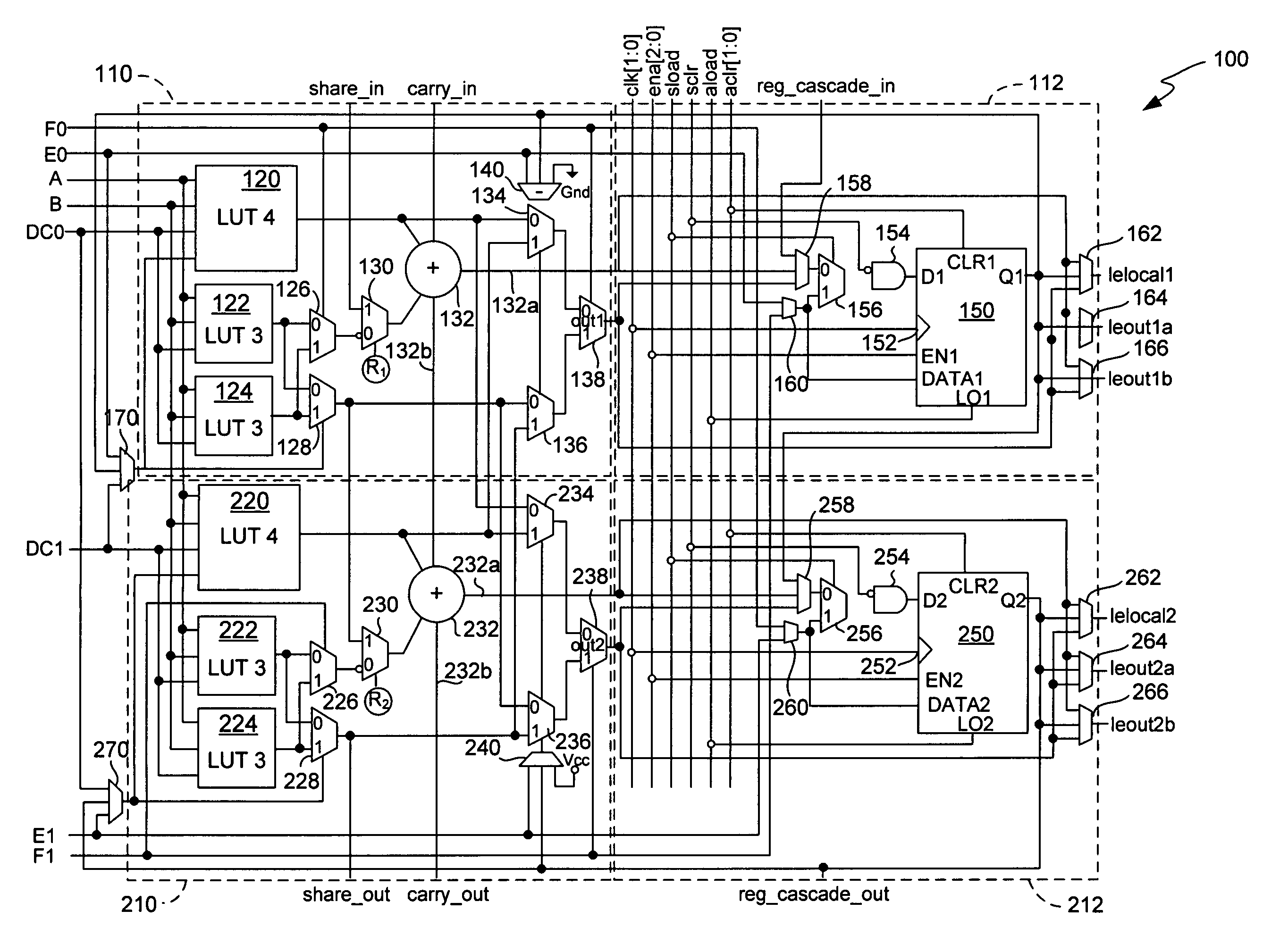
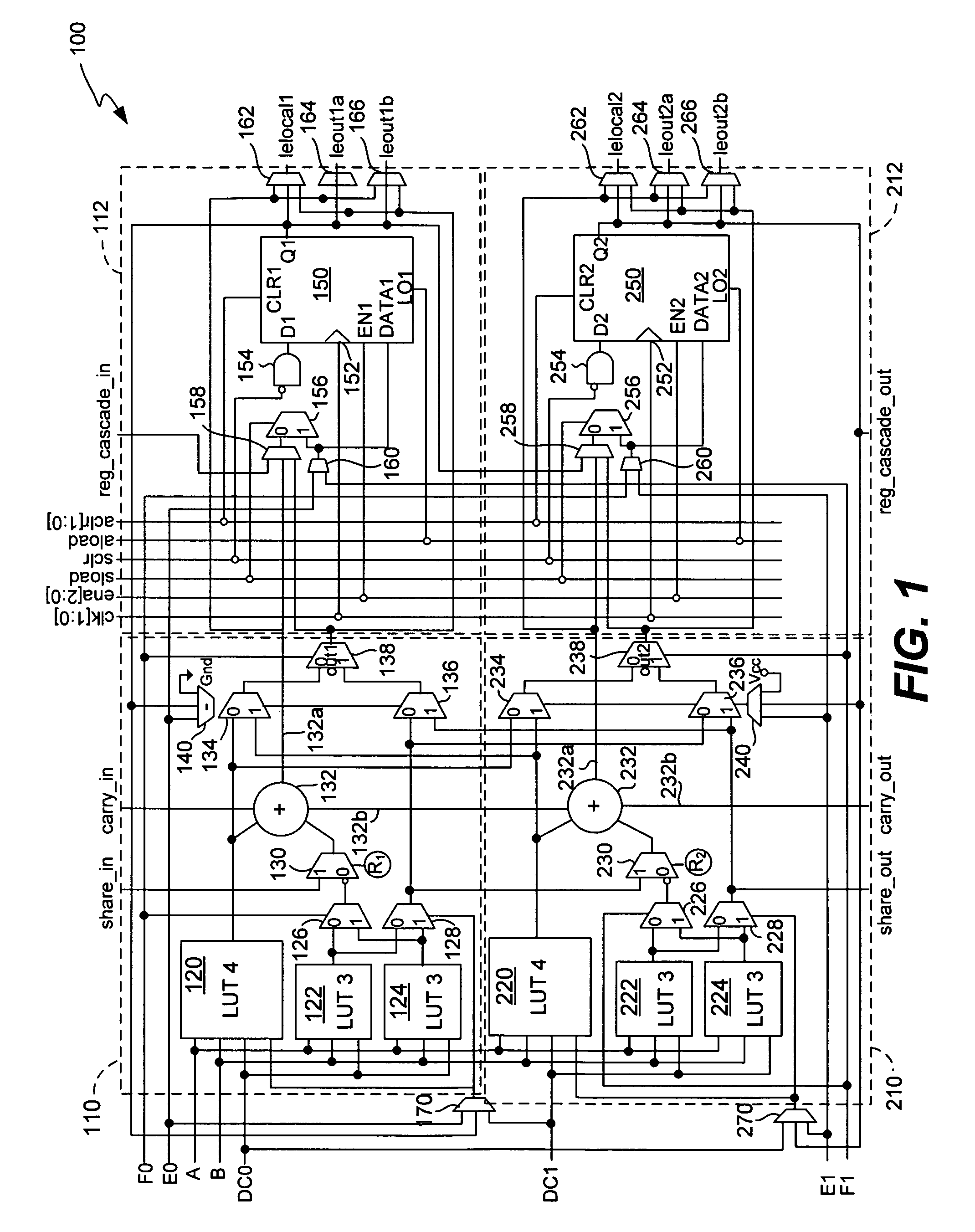
[0019]FIG. 1 illustrates a logic element (“LE”) 100 in accordance with the present invention. Logic element 100 includes a number of features, each discussed in detail below, to increase flexibility and efficiency thereof.

[0020]General Layout

[0021]To clarify description, LE 100 can be divided into four parts: a first arithmetic portion 110 associated with a first register portion 112 and a second arithmetic portion 210 associated with a second register portion 212. First arithmetic portion 110 and second arithmetic portion 210 each include 3 lookup tables (LUTs). First arithmetic portion 110 includes a first 4 input LUT (4LUT) 120, first 3LUT 122 and second 3LUT. 124, second arithmetic portion 210 includes second 4LUT 220, third 3LUT 222 and fourth 3LUT 224. First and second 3-LUT 122 and 124 drive 2, 2 input multiplexers (2MUXs) 126 and 128 of first arithmetic portion 110. Similarly, third 3LUT 222 and fourth 3LUT 224 each drive 2 input multiplexers (2MUXs) 226 and 228 of second ar...


PUM


Abstract

Disclosed is an LE that can provide a number of advantageous features. For example, the LE can provide efficient and flexible use of LUTs and input sharing. The LE may also provide for flexible use of one or more dedicated adders and include register functionality.

Description

CROSS-REFERENCE TO RELATED APPLICATIONS[0001]This application is a Continuation of U.S. patent application Ser. No. 10 / 810,117 entitled “Omnibus Logic Element” as filed on March 25, 2004 now U.S. Pat. No. 7,167,022 which is hereby incorporated by referenced.BACKGROUND OF THE INVENTION[0002]The present invention relates to logic elements for use with programmable logic devices or other similar devices.[0003]Programmable logic devices (“PLDs”) (also sometimes referred to as CPLDs, PALs, PLAs, FPLAs, EPLDs, EEPLDs, LCAs, FPGAs, or by other names), are well-known integrated circuits that provide the advantages of fixed integrated circuits with the flexibility of custom integrated circuits. Such devices are well known in the art and typically provide an “off the shelf” device having at least a portion that can be electrically programmed to meet a user's specific needs. Application specific integrated circuits (“ASICs”) have traditionally been fixed integrated circuits, however, it is pos...

Claims


Application Information

Patent Timeline
Patent Type & Authority Patents(United States)
IPC IPC(8): H03K19/177
CPCH03K19/17728H03K19/017581G06F5/01G06F7/50
Inventor SCHLEICHER, JAMESYUAN, RICHARDPEDERSEN, BRUCEKAPTANOGLU, SINANBAECKLER, GREGGLEWIS, DAVIDHUTTON, MIKELEE, ANDYSAINI, RAHULKIM, HENRY
Owner TAHOE RES LTD
Why Eureka
Try Eureka