
Aircraft propulsion system

a propulsion system and aircraft technology, applied in the field of aircraft, can solve the problems of engine performance decline, weight ratio, and turbo machine size reduction

Inactive Publication Date: 2009-06-02
PRATT & WHITNEY CANADA CORP
View PDF38 Cites 43 Cited by
  • Summary
  • Abstract
  • Description
  • Claims
  • Application Information

AI Technical Summary

Problems solved by technology

However, engine performance can decrease as the size of the turbo machine reduces, as does the thrust to weight ratio, since component thickness cannot be reduced proportionally with thrust.
The cost of engine components also does not scale linearly with thrust making the cost per unit of thrust for small engine relatively higher than for a bigger engine.

Method used


Image

  • Aircraft propulsion system
  • Aircraft propulsion system
  • Aircraft propulsion system

Examples


Embodiment Construction

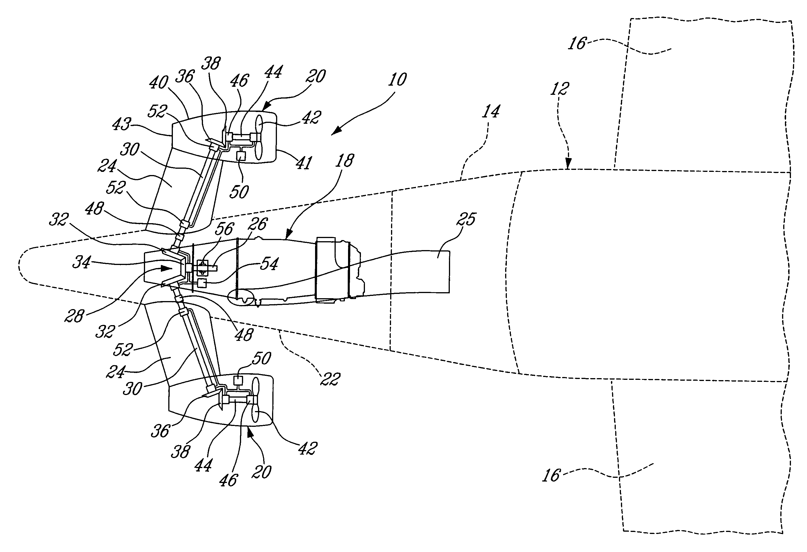
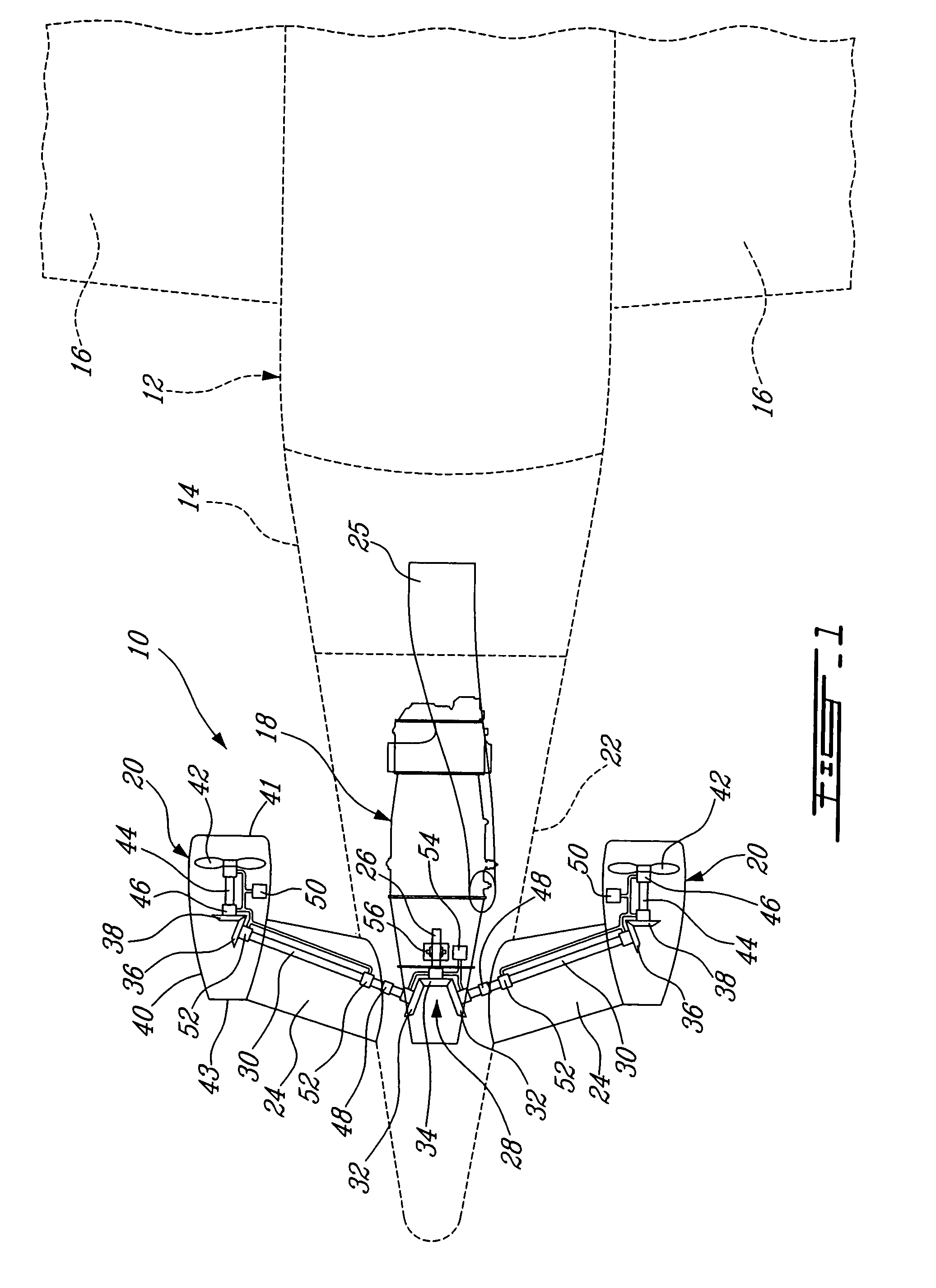
[0014]FIG. 1 illustrates an embodiment of an aircraft propulsion system 10 which is specifically well-adapted for small aircrafts conventionally propelled by small twin engines. However, it is understood that the propulsion system 10 could be applied to other types of conventional fixed wing aircrafts.

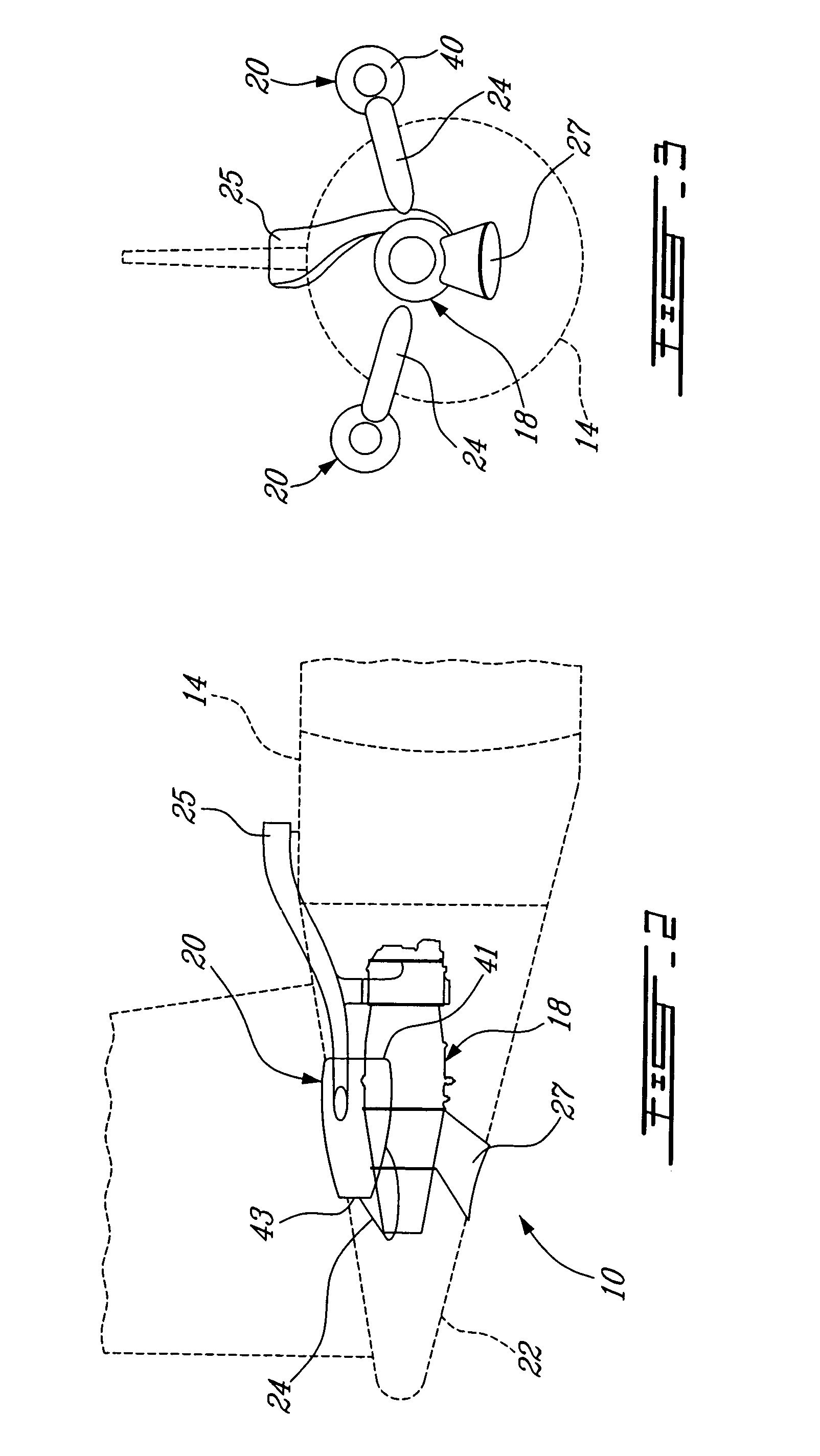
[0015]As shown in FIG. 1, the propulsion system 10 is integrated in a fixed wing aircraft 12 having a fuselage 14, and a pair of fixed wings 16 extending laterally from the fuselage 14. The propulsion system 10 generally comprises a single gas turbine engine 18 driving a pair of aerodynamic propulsion units 20 symmetrically arranged relative to a central longitudinal axis of the fuselage 14. The gas turbine engine 10 can be mounted in an engine compartment defined in the tail section 22 of the fuselage 14 rearwardly of the fixed wings 16. The propulsion units 20 are mounted outboard of the fuselage 14 at the distal end of short length pylons 24 extending laterally outwardly from oppose...


PUM


Abstract

An aircraft propulsion system comprises a power plant driving a number of outboard propulsion units to propel a fixed wing aircraft.

Description

TECHNICAL FIELD[0001]The invention relates generally to aircrafts and, more particularly, to an improved aircraft propulsion system.BACKGROUND OF THE ART[0002]Small twin-engine aircraft require the same reliability, performance, specific weight and cost for their low thrust turbofan engines as are required for much larger units. However, engine performance can decrease as the size of the turbo machine reduces, as does the thrust to weight ratio, since component thickness cannot be reduced proportionally with thrust. The cost of engine components also does not scale linearly with thrust making the cost per unit of thrust for small engine relatively higher than for a bigger engine.[0003]Accordingly, there is a need to provide an improved aircraft propulsion system which addresses these.SUMMARY OF THE INVENTION[0004]It is therefore an object of this invention to provide an improved aircraft propulsion system.[0005]In one aspect, the present invention provides an aircraft propulsion sys...

Claims


Application Information

Patent Timeline
Patent Type & Authority Patents(United States)
IPC IPC(8): B64D27/00
CPCB64D27/14B64D35/04
Inventor BRAND, JOSEPH HORACEDOOLEY, KEVINDOWHAN, MICHAELYOUSSEF, NASHEDHARVEY, RICHARDSAVAGE, WILLIAM
Owner PRATT & WHITNEY CANADA CORP
Learn More