Backlight module and scattering module for same

a backlight module and scattering technology, applied in lighting elements, lighting and heating apparatuses, instruments, etc., can solve the problem of a larger linear density along the horizontal or vertical axis than along the diagonal direction

Active Publication Date: 2009-06-02
AU OPTRONICS CORP
View PDF6 Cites 5 Cited by
  • Summary
  • Abstract
  • Description
  • Claims
  • Application Information

AI Technical Summary

Benefits of technology

[0011]One objective of this invention is to provide a scattering module adapted for a backlight module. The backlight module includes a plurality of light sources. The light sources are located on a side of the scattering module, and include a first light source, a second light source and a third light source. The second light source is arranged along a first direction of the first light source with a first spacing formed therebetween. The third light source is arranged along a second direction of the first light source with a second spacing formed therebetween. The first spacing is smaller than the second spacing, while the first direction is different from but is substantially not perpendicular to the second direction. The scattering module of this invention comprises a plurality of scattering elements. The scattering elements present a first linearly arranged density in the first direction and a second linearly arranged density in the second direction, with the first linearly arranged density is smaller than the second linearly arranged density. In this way, the light from the backlight module is projected to the display panel uniformly without incurring a non uniform brightness distribution.
[0012]Another objective of this invention is to provide a backlight module, which comprises a plurality of light sources and the aforesaid scattering module. The light sources are disposed on a side of the scattering module and include a first light source, a second light source and a third light source. The second light source is arranged along a first direction of the first light source with a first spacing formed therebetween. The third light source is arranged along a second direction of the first light source with a second spacing formed therebetween. The first spacing is smaller than the second spacing, while the first direction is different from but is substantially not perpendicular to the second direction. The scattering module comprises a plurality of the scattering elements, which present a first linearly arranged density and a second linearly arranged density in directions parallel to the first direction and the second direction respectively, with the first linearly arranged density smaller than the second linearly arranged density. In this way, the light from the backlight module is projected onto the display panel uniformly without incurring a non uniform brightness distribution.

Problems solved by technology

However, in such a prior art structure, the dot pattern arrangement only takes into account the relative relationships between the individual light sources arranged along the same horizontal or vertical axis, but ignores the fact that the maximum distance between the individual light sources exists in the diagonal direction, thus causing a larger linearly density along the horizontal or vertical axis than that along the diagonal direction.

Method used


Image

  • Backlight module and scattering module for same
  • Backlight module and scattering module for same
  • Backlight module and scattering module for same

Examples


first embodiment

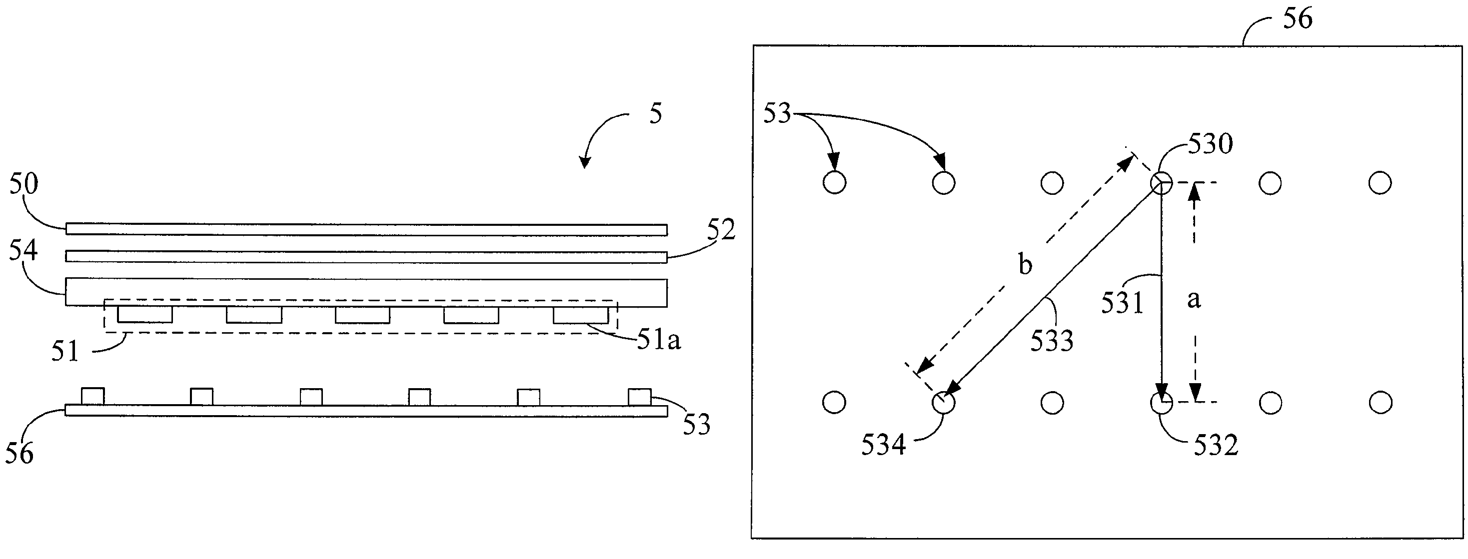
[0023]this invention is a backlight module 5, of which a cross-sectional view is depicted in FIG. 5. The backlight module 5 comprises a brightness enhancement film (BEF) 50, a diffuser sheet (DS) 52, a diffuser plate (DP) 54, a scattering module 51, a plurality of light sources 53 and a reflector 56 from top to bottom in FIG. 5. The scattering module 51 further comprises a plurality of scattering elements. In this embodiment, these scattering elements are a plurality of dot patterns 51a disposed on the bottom surface of the diffuser plate 54. The plurality of light sources 53 are light emitting diodes (LEDs) disposed on the reflector 56 facing towards the scattering elements. In other words, the plurality of light sources 53 are disposed on a side of the scattering module 51.

[0024]The top view of the reflector 56 and the light sources 53 in the backlight module 5 is depicted in FIG. 6. The plurality of light sources 53 include a first light source 530, a second light source 532 and ...

second embodiment

[0029]this invention is also a backlight module. The scattering module 51′ of this backlight module comprises scattering elements different from those in the previous embodiments. FIG. 9 depicts the bottom view of a diffusion plate 54 and the scattering elements 51a′ of this backlight module. As shown, the scattering elements 51a′ of the scattering module 51′ all have an equal area and a circular shape. The scattering elements includes a first dot pattern 510′, a second dot pattern 512′ and a third dot pattern 514′, which correspond to a first light source 530, a second light source 532 and a third light source 534 respectively. The line connecting the first dot pattern 510′ and the second dot pattern 512′ is parallel to a first direction 531, with two adjacent dot patterns along the first direction 531 with a first distance x, i.e., the first dot pattern 510′ and the second dot pattern 512′ has the first distance x. The line connecting the first dot pattern 510′ and the third dot p...


PUM


Abstract

A scattering module and a backlight module comprising the scattering module are provided. The backlight module includes a plurality of light sources, while the scattering module includes a plurality of scattering elements. The scattering elements are disposed correspondingly to the light sources so that the scattering elements have different linearly arranged densities in different directions. Thereby, the light generated from the backlight module would be projected onto the display panel evenly with a uniform brightness.

Description

[0001]This application claims priority to Taiwan Patent Application No. 096130752 filed on Aug. 20, 2007, the disclosures of which are incorporated herein by reference in their entirety.CROSS-REFERENCES TO RELATED APPLICATIONS[0002]Not applicable.BACKGROUND OF THE INVENTION[0003]1. Field of the Invention[0004]The present invention relates to a scattering module and a backlight module comprising the same and more particularly, the present invention relates to a scattering module structure capable of rendering the brightness of a backlight module more uniform without incurring a non uniform distribution of brightness on a display panel.[0005]2. Descriptions of the Related Art[0006]Liquid crystal displays (LCDs) are full color display devices that utilize the liquid crystal technology with advantages such as low power consumption, low radiation, small footprints, is lightweight and is flexible in size. Therefore, LCDs have been used in many electronic products that incorporate display ...

Claims


Application Information

Patent Timeline
Patent Type & Authority Patents(United States)
IPC IPC(8): F21V33/00
CPCG02F1/133603G02F1/133606
Inventor TSAI, SHAU-YULIN, YU-CHUAN
Owner AU OPTRONICS CORP
Why Eureka
Try Eureka