
Piece conveyor for conveying parts of a carcase

a conveyor and carcass technology, applied in the field of pieces, can solve the problems of uncertain further conveying in the processing line, unhygienic, cumbersome, expensive and imprecise, etc., and achieve the effect of simple and efficien

Inactive Publication Date: 2009-08-27
K J MASKINFABEN
View PDF5 Cites 2 Cited by
  • Summary
  • Abstract
  • Description
  • Claims
  • Application Information

AI Technical Summary

Benefits of technology

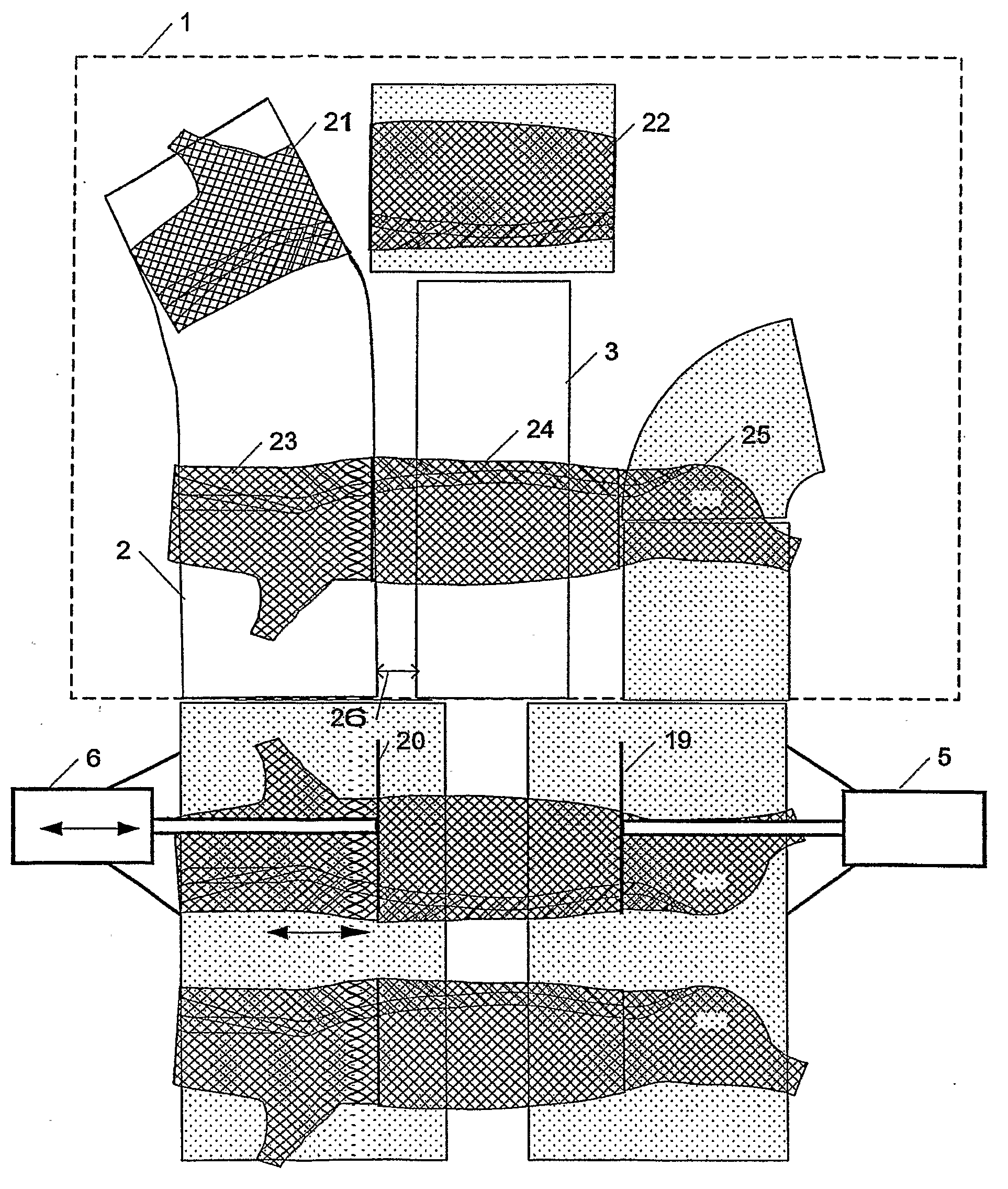
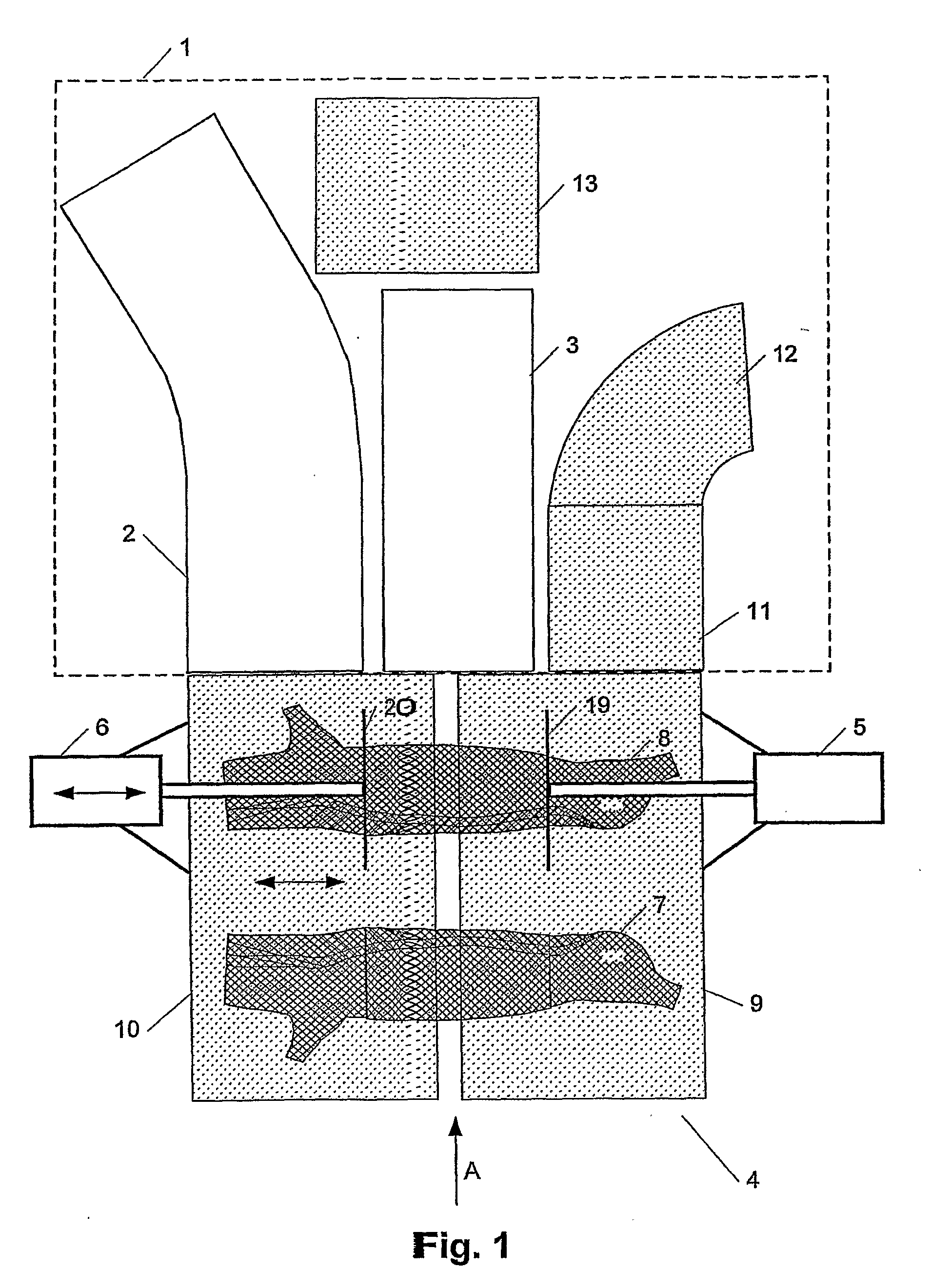
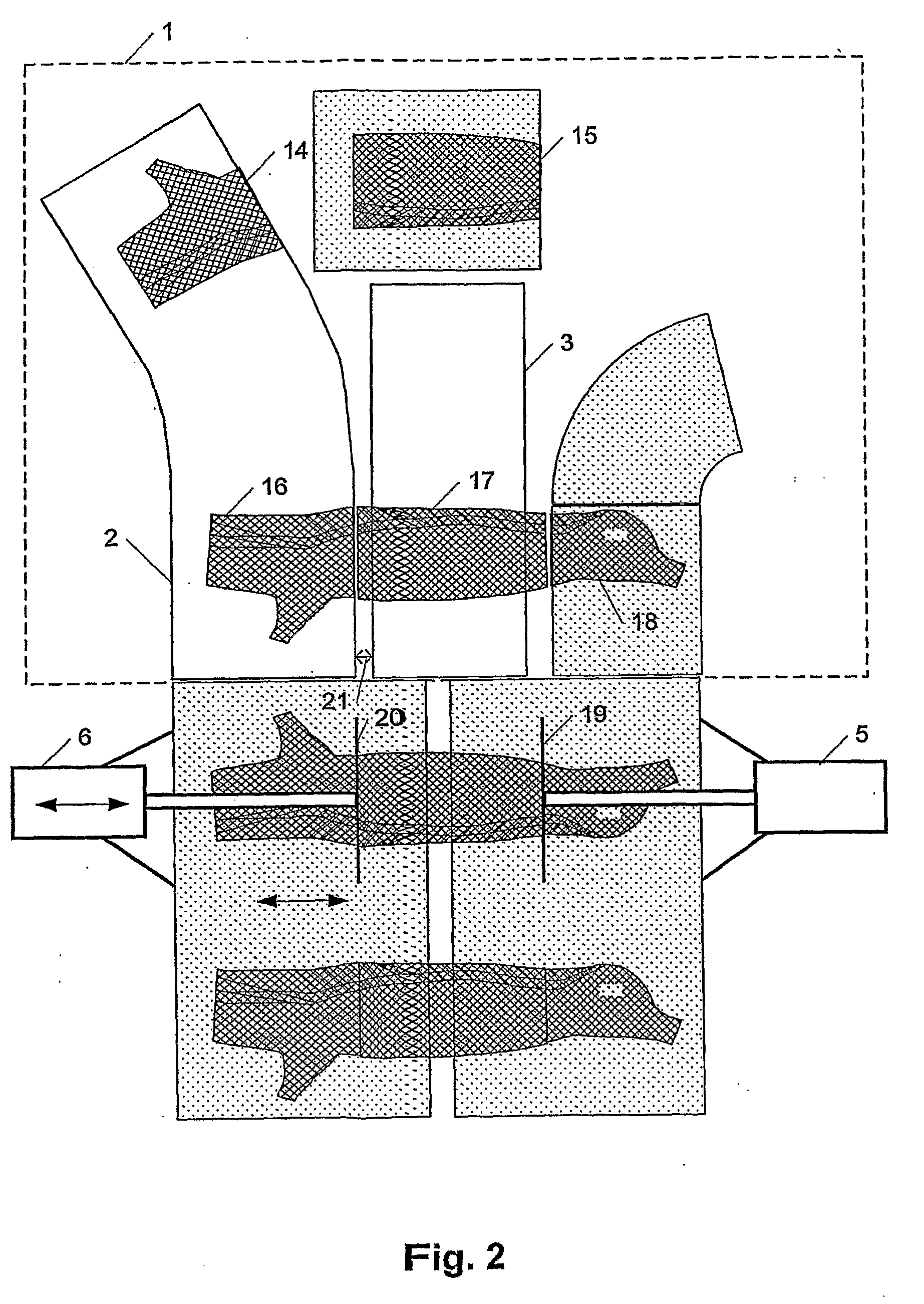
[0008]This is obtained by a piece conveyor for separately conveying parts of a carcase, wherein the piece conveyor is adapted to be arranged in continuation of a cutting unit, the cutting unit comprising a dividing unit being movable in a direction transverse to the conveying direction for dividing the carcase into at least a first part and a second part, and wherein the piece conveyor comprises at least two conveyors for separately conveying the first part and the second part, respectively. At least one of the at least two conveyors is movable transversally to the conveying direction, the conveyor thereby being movable according to the size of the parts. The movable conveyors are provided with a mutual interconnecting mechanism for simultaneous movement of the at least two conveyors transversally to the conveying direction, said mutual interconnecting mechanism being designed in such a way that the distances of movement of the at least two conveyors transversally to the conveying direction may differ. Thereby it is ensured, purely by moving the conveyors, that the parts are supported in the best possible way during further conveying, since the parts may be supported fully or below the middle of the part, the projections from the conveyor thereby being uniform in both sides. Thereby manual adjustment of the parts is avoided.
[0009]The simultaneous movement of the at least two conveyors may be performed by mechanically connecting the first conveyor of the piece conveyor to the movable dividing unit of the dividing system. This is a relatively cost effective and simple way of providing the desired simultaneous movement.
[0013]All of the three conveyors may be movable transversally to the conveying direction. Thereby even further flexibility in setting the piece conveyor in accordance with a part of a particular size is obtained.
[0014]In one embodiment the interconnecting mechanism may be designed in such a way that the ratio between the distances of movement for the two conveyors is at least substantially constant. This may be a simple and efficient manner of obtaining a correct symmetrical position of the conveyors relatively to the parts.
[0016]In one embodiment the movable curved conveyor(s) may have an at least substantially fixed outlet end and a movable inlet end. This makes it possible to locate the piece conveyor in existing processing conveyors.

Problems solved by technology

In either case this will result in a very uncertain further conveying in the processing lines, i.a. due to uncertainty in the exact positions of the parts on the subsequent conveyor belts.
This is unhygienic, cumbersome, expensive as well as imprecise.

Method used


Image

  • Piece conveyor for conveying parts of a carcase
  • Piece conveyor for conveying parts of a carcase
  • Piece conveyor for conveying parts of a carcase

Examples


Embodiment Construction

[0028]In FIG. 1 is shown a piece conveyor 1 comprising a curved conveyor 2 and a straight conveyor 3, as well as conveyors 11, 12 and 13. The piece conveyor is arranged in continuation of a dividing system 4 having two fixedly mounted cutting units 5, 6, the cutting units comprising a dividing unit 19, 20 in the form of, e.g., a saw, and at least one of the dividing units 19, 20 being movable in a direction being transverse to the conveying direction, shown by arrow A. On the cutting part is shown two carcases 7, 8. The carcases are conveyed past the dividing units 19, 20, whereby the carcases are divided into two parts. The conveyor 10 is movable in a direction perpendicular to the conveying direction, along with the cutting unit 6. The piece conveyor comprising the curved conveyor 2 and the straight conveyor 3, as well as the conveyors 11, 12 and 13 are for the purpose of conveying the parts further on in the processing lines.

[0029]FIG. 2 shows a separation of the parts 14 and 15,...


PUM


Abstract

The invention relates to a piece conveyor for separately conveying parts of a carcase, wherein the piece conveyor is adapted to be positioned in continuation of a cutting unit comprising a dividing unit being movable in a direction transversally to the conveying direction for dividing the carcase into at least a first part and a second part, and wherein the piece conveyor comprises at least two conveyors for separately conveying the first part and the second part, respectively. At least one of the at least two conveyors of the piece conveyor is movable in a direction being transverse to the conveying direction, the conveyor thereby being movable according to the size of the parts. The movable conveyors are provided with a mutual interconnecting mechanism for simultaneous movement of the at least two conveyors transversally to the conveying direction, said mutual interconnecting mechanism being designed in such a way that the distances of movement of the at least two conveyors transversally to the conveying direction may differ. Thereby it is ensured, purely by moving the conveyors, that the parts are supported in the best possible way during further conveying, since the parts may be supported fully or below the middle of the part, the projections from the conveyor thereby being uniform in both sides. Thereby manual adjustment of the parts is avoided.

Description

FIELD OF THE INVENTION[0001]The present invention relates to a piece conveyor fore separately conveying parts of a carcase. The invention further relates to a method for separately conveying parts of a carcase.BACKGROUND OF THE INVENTION[0002]Primary cutting of animal carcases is often performed in a cutting unit comprising a cutting system with two saws, the carcase thereby being divided into three parts; front end part, middle part and back end part. The two cutting saws are arranged in such a way that they perform parallel incisions in the conveying direction of the carcase. The sizes of the carcases are non-uniform, and in order to obtain an optimal yield from the carcase it is necessary to be able to vary the distance between the two incisions, the incisions thereby being adaptable to the individual carcase. In continuation of the cutting unit a piece conveyor is arranged, the piece conveyor comprising a front end part conveyor, a middle part conveyor and a back end part convey...

Claims


Application Information

Patent Timeline
IPC IPC(8): A22B5/20A22B5/00A22B7/00B65G21/14
CPCA22B5/0029B65G21/14A22B7/001
Inventor BUSCH, FINN MAAG
Owner K J MASKINFABEN
Learn More