
Method of operating a fuel injector

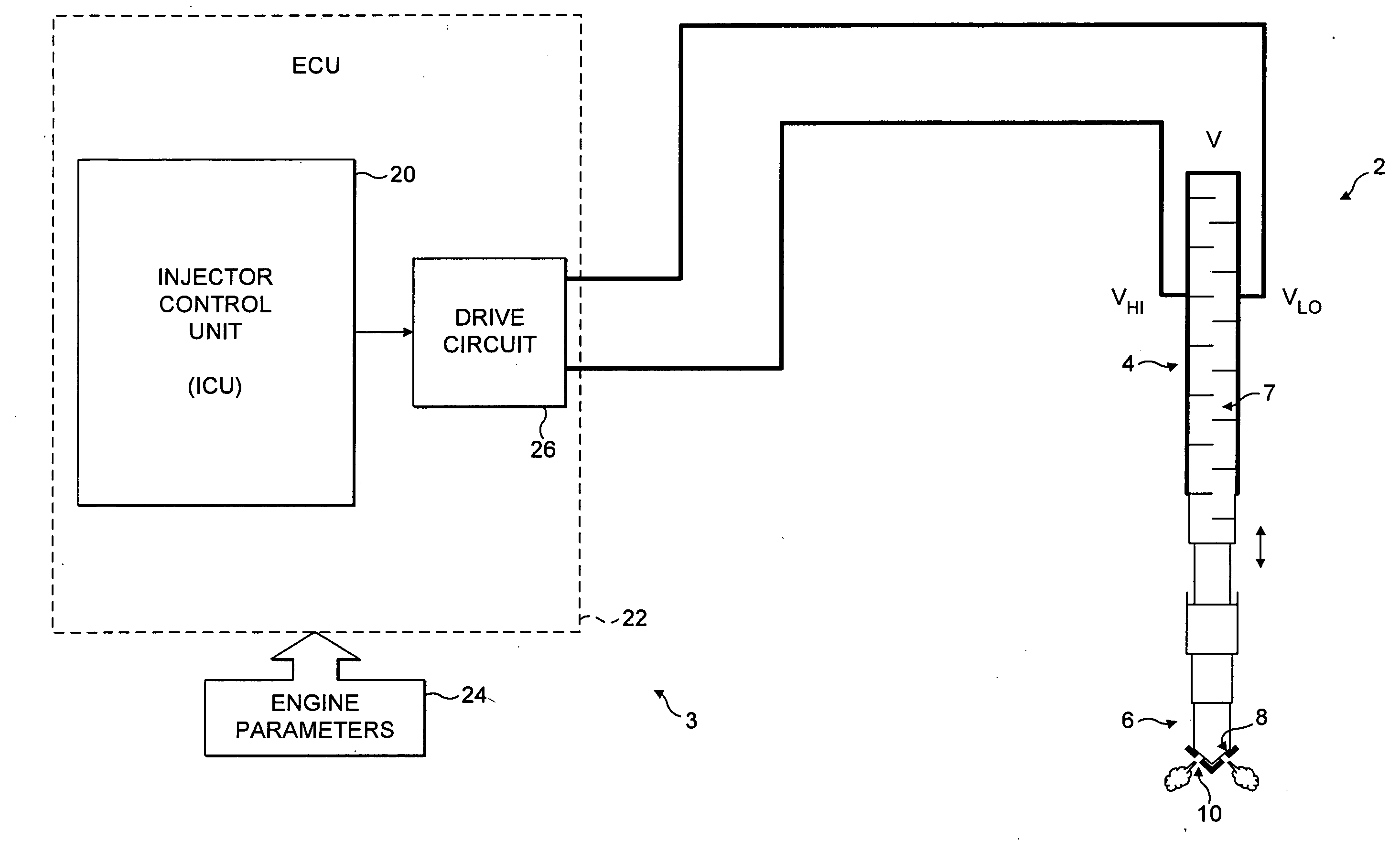
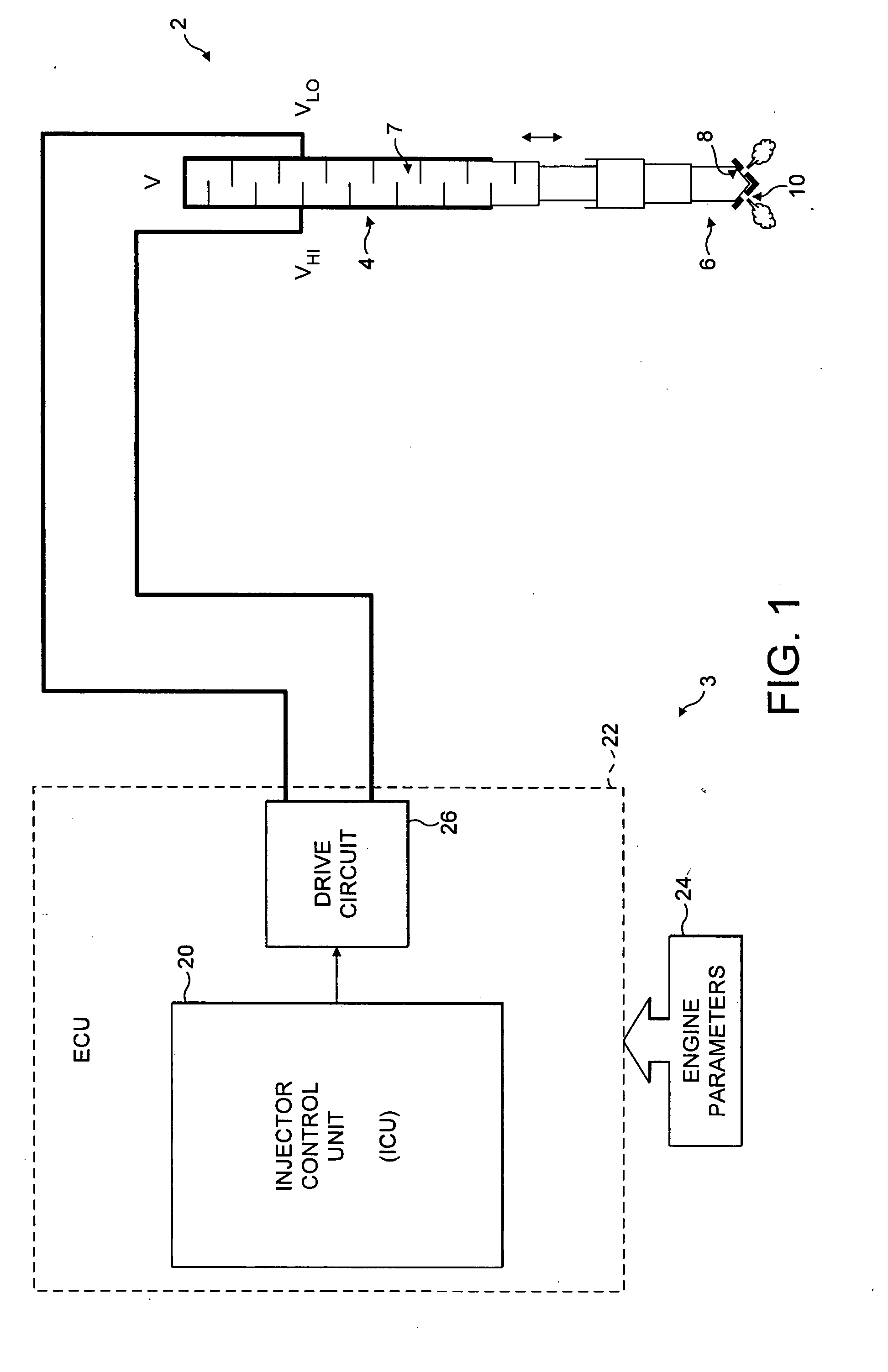
a fuel injector and fuel technology, applied in the direction of electrical control, process and machine control, instruments, etc., can solve the problem of apparent noise of the injector, and achieve the effect of reducing the volume of fuel

Inactive Publication Date: 2007-11-29
DELPHI INT OPERATIONS LUXEMBOURG S A R L
View PDF7 Cites 11 Cited by
  • Summary
  • Abstract
  • Description
  • Claims
  • Application Information

AI Technical Summary

Benefits of technology

[0011]By configuring the drive pulse such that its dominant frequencies are remote from the or each resonant frequency of the injector installation, a substantial reduction in noise is achieved.
[0013]In one embodiment, in order to reduce the volume of fuel delivered by the injector during a first series of successive injection events, the method includes reducing the injector on time period to a predetermined injector on time threshold value and, for subsequent reductions in fuel delivery volume, holding the injector on time period substantially constant and thereafter reducing the discharge,time period.
[0014]For a subsequent series of successive injection events, the injector on time period may be held substantially constant, the discharge time period may be held substantially constant, and the peak discharge / charge current amplitude may be reduced to a predetermined peak current threshold value in order to further reduce the volume of fuel that is delivered by the injector over the subsequent series of successive injection events.
[0015]In an alternative embodiment, in order to reduce the volume of fuel delivered by the injector during a first series of successive injection events, the method includes reducing the injector on time period to a predetermined injector on time threshold value and, for subsequent reductions in fuel delivery volume, holding the injector on time period substantially constant and thereafter reducing the peak discharge / charge current amplitude to a predetermined peak current threshold value. In this embodiment, for a subsequent series of successive injection events, the injector on time period may be held substantially constant, the peak discharge / charge current amplitude may be held substantially constant, and the discharge time period may be reduced in order to further reduce the volume of fuel that is delivered by the injector.
[0016]In another embodiment, where an injection comprises a plurality of injector drive pulses, for example in the form of first and second pilot drive pulses and a single main drive pulse, the temporal separation between successive drive pulses may be selected so as to modify the frequency domain signature of the drive pulse sequence such that a maximum of the frequency domain signature is remote from the determined resonant frequency of the injector installation. This provides further flexibility in modifying the characteristics of an injection event in order to achieve a reduction in emitted noise.

Problems solved by technology

Although piezoelectric injectors are adept at delivering precise quantities of fuel with accurate timing, they also have associated disadvantages.
However, at low engine speeds, particularly at an engine idle operating condition and with the bonnet / hood raised, the audible injector noise is apparent.

Method used


Image

  • Method of operating a fuel injector
  • Method of operating a fuel injector
  • Method of operating a fuel injector

Examples


first embodiment

[0070]the invention will now be described with reference to FIG. 8. In this embodiment, for injection events in which a relatively high volume of fuel is required to be delivered, for example during medium to high engine load conditions, the ICU 20 modifies the delivery volume by increasing or decreasing the injector on time appropriately, as can be seen on FIG. 8 by the injector drive pulses 200, 202 and 204 having successively decreasing values of injector on time TON—1, TON—2 and TON—3.

[0071]The dwell time for the drive pulse 204 represents the minimum dwell time as imposed by the switching requirements of the injector drive circuit 26. In order to decrease the delivery volume further, the dwell time must remain at this value so further reduction of injector on time results in the reduction of the discharge time TDISCHARGE, as can be seen by the drive pulses 206, 208 and 210 having injector on times of TON—4, TON—5 and TON—6, respectively.

[0072]It should be noted that for each of...

second embodiment

[0083]FIGS. 10 and 11 show the invention which is a specific implementation of the tuned drive pulse concept described above. In FIG. 10, a drive pulse 300 is shown for a typical injection event that corresponds approximately to a medium engine load operating condition. As can be seen, the injector is discharged from a starting voltage level V1 to a predetermined voltage level V2 at which point the voltage remains for a significant dwell period before the injector is recharged back to the starting voltage level V1 to terminate the injection event.

[0084]Also shown in FIG. 10 is a typical drive pulse 302 that corresponds to a low engine load operating condition, for example when the engine is running at idle. As can be seen, the injector is discharged from the starting voltage level V1 at the same rate as for the drive pulse 300, but to a voltage level V3 which is greater than V2. The voltage remains at V3 for a very short dwell period, which is the minimum permissible dwell period as...

third embodiment

[0090]the invention is described below with reference to FIG. 13 which shows a typical injector voltage drive profile 400 for a first pilot injection event 402 followed by a second pilot injection event 404 followed by a main injection event 406.

[0091]In FIG. 14, a frequency domain signature 410 of the drive voltage profile 400 is shown to include peaks in energy at approximately 4.5 kHz and 7.5 kHz. However, in order to achieve further reductions in noise emitted from the injectors, particularly at engine idle operating conditions, in this embodiment of the invention the separation between the first pilot injection event 402 and the second pilot injection event 404, and between the second pilot injection event 404 and main injection event 406 is modified so as to affect directly the energy composition of the frequency signature.

[0092]For example, by appropriate modification of the separation between the pilot injections and the main injection, the frequency signature may be altered...


PUM


Abstract

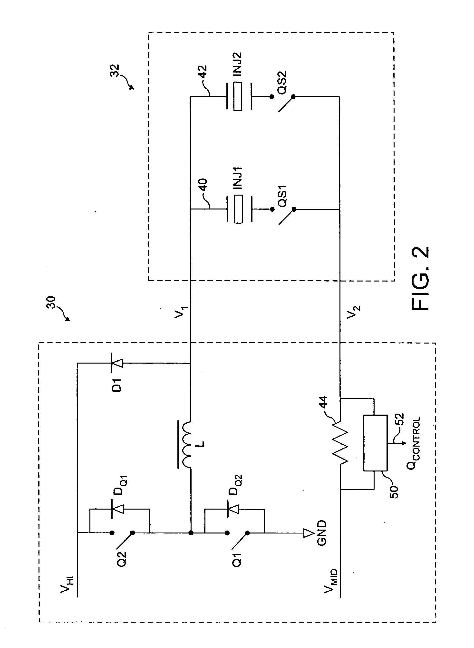
A method of operating a fuel injector having a piezoelectric actuator operable by applying a drive pulse thereto, wherein the drive pulse has a frequency domain signature. The method includes i) determining at least one resonant frequency of an injector installation in which the injector is received, in use, and ii) modifying the drive pulse such that a maximum of the frequency domain signature thereof is remote from the determined resonant frequency of the injector installation.

Description

TECHNICAL FIELD[0001]The invention relates to a method of operating a fuel injector. More specifically, the invention relates to a method of operating a piezoelectrically actuated fuel injector in order to reduce the level of noise that is generated by the injector.BACKGROUND TO THE INVENTION[0002]In a direct injection internal combustion engine, a fuel injector is provided to deliver a charge of atomised fuel into a combustion chamber prior to ignition. Typically, the fuel injector is mounted in a cylinder head of an engine with respect to the combustion chamber such that a tip of the injector protrudes slightly into the chamber to permit the fuel charge to be delivered thereto.[0003]One type of fuel injector that is particularly suited for use in a direct injection engine is a so-called piezoelectric injector. Such an injector allows precise control of the timing of an injection event and of the total volume of fuel that is delivered to the combustion chamber during the injection ...

Claims


Application Information

Patent Timeline
Patent Type & Authority Applications(United States)
IPC IPC(8): H01L41/00F02M51/00
CPCF02D41/2096
Inventor HOPLEY, DANIEL J.NOYCE, STEPHEN A.ALMOND, COLIN
Owner DELPHI INT OPERATIONS LUXEMBOURG S A R L
Learn More