Shaft-to-roller attachment for clinker grinder roller

a technology for grinding rollers and driveshafts, which is applied in the field of grinding rollers for grinding wheels, can solve the problems of virtually unweldable cast irons, hot tears and cracking, and particularly difficult design challenges, so as to avoid hot tears and cracking, and reduce stress concentration

Active Publication Date: 2016-06-28
DIAMOND POWER INT
View PDF20 Cites 3 Cited by
  • Summary
  • Abstract
  • Description
  • Claims
  • Application Information

AI Technical Summary

Benefits of technology

[0007]In overcoming the drawbacks and other limitations of the related art, the present invention provides an improved grinder roller assembly and an improved method of forming a grinder roller assembly. In one embodiment of the invention, the insert plate has an outer surface that is noncircular and with smooth projections, the shaft and insert plate are attached together with fasteners, and the clinker grinder roller is cast directly over the insert plate which is done at a high metal cast temperature. The smooth projections on the insert reduce the stress concentration in the casting at the perimeter of the insert to help avoid hot tears and cracking during solidification and cooling of the cast iron. The use of fasteners eliminates the need to weld the insert plate to the shaft, resulting in an improved grinder roller assembly that is able to function for long periods without the insert plate pulling away and disengaging from the clinker grinder roller, and without the development of cracks.

Problems solved by technology

Clinker grinder machines operate in a hot, corrosive, and erosive environment and experience severe operating loads, yet must operate for long periods without failure.
A particularly difficult design challenge is providing an attachment between the grinder roller and the drive shaft that rotates the roller.
This class of cast irons is virtually unweldable, so welding a roller made of such alloys to the driving shaft is not an option.
First, the outer surface of the insert plate tends to pulls away from the inner surface of the clinker grinder roller during the welding of the shaft to the insert plate which can loosen the attachment between the insert plate and the roller.
Second, the shims eventually wear and loosen.
Third, since the roller cavity is a cast, in most cases the inner surfaces of the roller cavity are not flat which reduces the load bearing area between the insert plate and the roller.
These three problems cause the clinker grinder roller to disengage from the insert plate, creating a loose fit which eventually leads to the failure of the device.

Method used


Image

  • Shaft-to-roller attachment for clinker grinder roller
  • Shaft-to-roller attachment for clinker grinder roller
  • Shaft-to-roller attachment for clinker grinder roller

Examples


Embodiment Construction

[0017]The following description is merely exemplary in nature and is not intended to limit the present disclosure, application, or uses. The term “substantially” used herein with reference to a physical parameter or quantity includes a variation in the recited physical parameter or quantity of an amount that is insubstantially different from a recited physical parameter or quantity for an intended purpose or function.

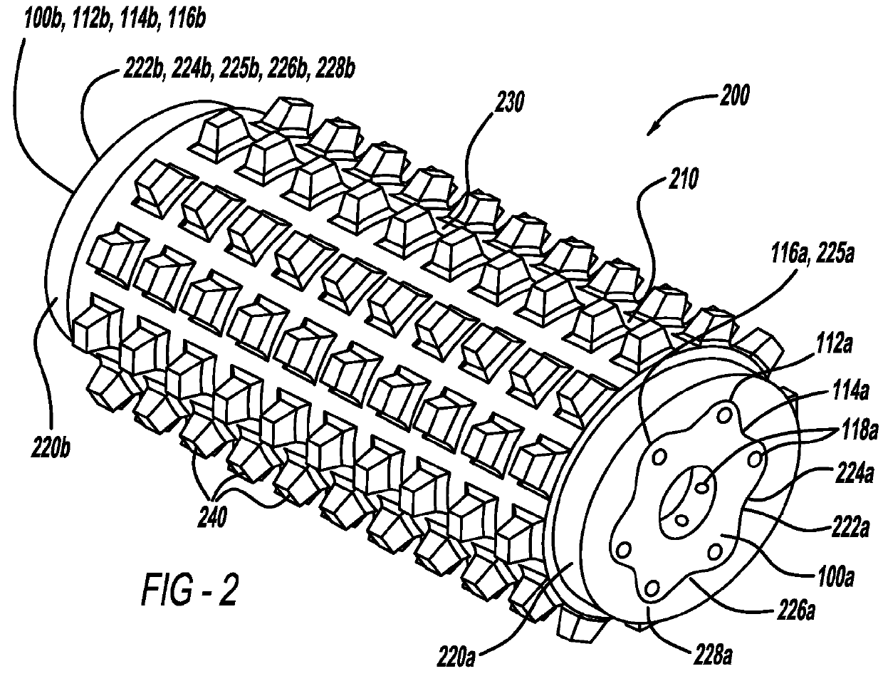
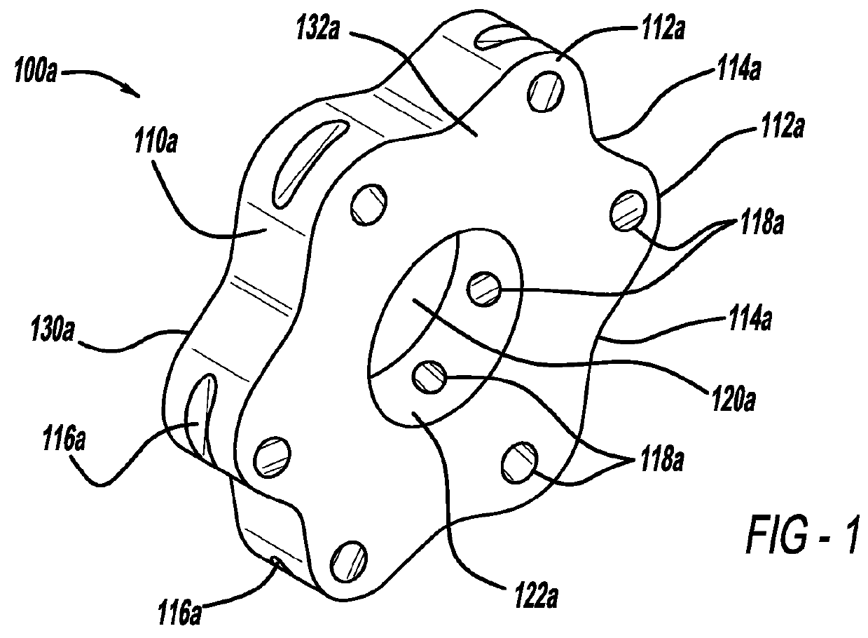
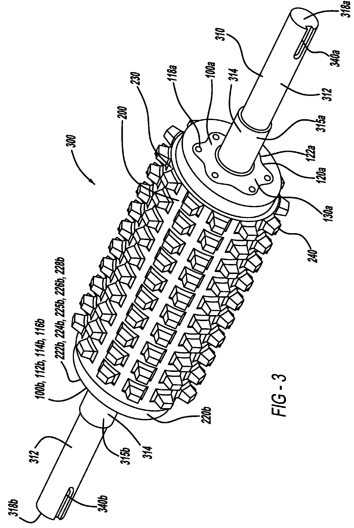
[0018]FIG. 1 illustrates an insert plate 100a in accordance with some embodiments of the present invention. The insert plate 100a may be cast into its net shape, or machined from wrought material. The insert plate 100a has a noncircular outer surface 110a that is smooth or substantially smooth. As used herein, “smooth” means lacking sharp edges. In some embodiments, the insert plate 100a has on its outer surface 110a one or more projections, for example between one and ten lobes 112a. Between the lobes 112a are a corresponding number of troughs 114a. FIG. 1 shows a pref...


PUM

PropertyMeasurementUnit
diameteraaaaaaaaaa
temperatureaaaaaaaaaa
diameteraaaaaaaaaa

Abstract

A grinder roller assembly and a method of forming a grinder roller assembly are provided. The grinder roller assembly includes an elongated shaft that comprises a shaft outer surface. The grinder roller assembly further includes an insert plate. The insert plate has a plate outer surface that is noncircular and substantially smooth. The insert plate further has a plate opening that defines a plate inner surface and is configured to receive the elongated shaft. The grinder roller assembly further includes a roller having a roller opening that defines a roller inner surface that cooperates with the plate outer surface. The grinder roller assembly further includes at least one fastener that attaches the insert plate to the elongated shaft.

Description

BACKGROUND[0001]1. Field of the Invention[0002]The present invention generally relates to a roller for a clinker grinder. More specifically, the present invention relates to an attachment for a clinker grinder roller to a related drive shaft.[0003]2. Description of the Related Art[0004]Large coal burning power plants and furnaces produce ash as a combustion byproduct. The ash typically accumulates as a powder and in large chunks referred to as “clinkers.” A clinker grinder machine is used to grind the ash clinkers into small particles so that the ash can be transported for disposal through pipes pneumatically or hydraulically. Clinker grinders typically have one or two large drum rollers with grinding teeth on the surface of the rollers. The rollers are rotated so that the grinding teeth grind the clinkers. Clinker grinder machines operate in a hot, corrosive, and erosive environment and experience severe operating loads, yet must operate for long periods without failure. A particul...

Claims


Application Information

Patent Timeline
Patent Type & Authority Patents(United States)
IPC IPC(8): B02C4/08B02C4/30B21B27/03B21B31/08F23J1/00A01D82/00B27G13/02A01F12/40A01D43/10
CPCB02C4/08B02C4/30B21B27/03B21B31/08F23J1/00A01D43/10A01D82/00A01F12/40B27G13/02F23J2900/01003Y10T29/49547
Inventor HABIB, TONY F.HONAKER, ROBERT W.SOWERS, CLINT M.LUKEZICH, STEPHEN J.HARDY, BRECK J.
Owner DIAMOND POWER INT
Why Eureka
Try Eureka