Optical lens structure

A technology of lens structure and curved surface, applied in lighting devices, lighting device parts, refractors, etc., can solve the problem that flood lighting equipment cannot be directly applied

Inactive Publication Date: 2011-09-21
CAL COMP ELECTRONICS +1
View PDF3 Cites 2 Cited by
  • Summary
  • Abstract
  • Description
  • Claims
  • Application Information

AI Technical Summary

Problems solved by technology

[0003] However, light-emitting diodes are point light sources, and their light source characteristics have high directivity, so they cannot be directly applied to flood lighting equipment

Method used


Image

  • Optical lens structure
  • Optical lens structure
  • Optical lens structure

Examples


Embodiment Construction

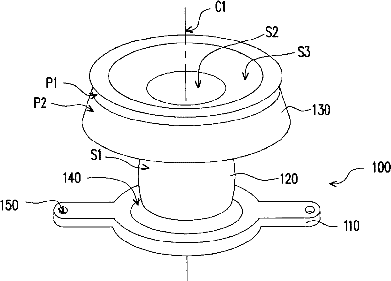
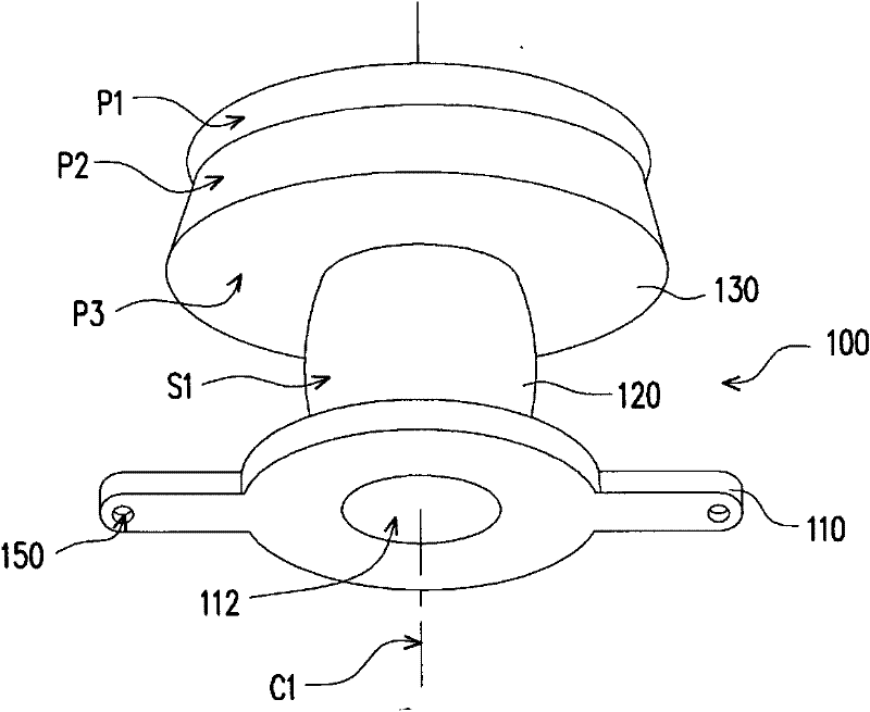
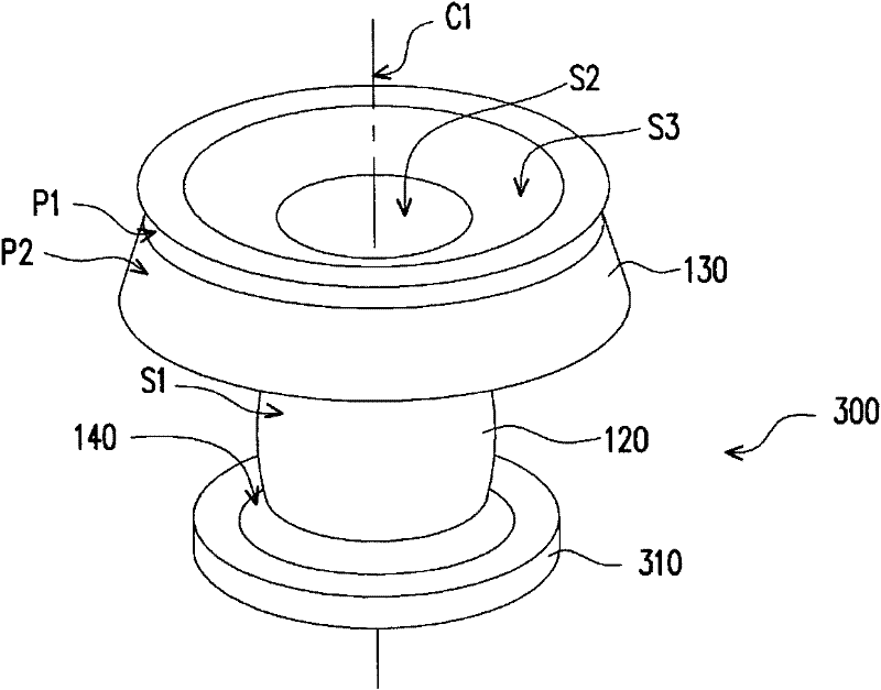
[0036] Figure 1A and Figure 1B It is a perspective view of a lens structure in different viewing angles according to an embodiment of the present invention. Figure 2A and Figure 2B It is a perspective view of a lens structure of another embodiment of the present invention at different viewing angles. image 3 for Figure 1A Side view of the lens structure. Please also refer to Figure 1A to Figure 3 , the lens structure 100 is suitable for directing the light emitted by a light source 200 into multiple directions. In this embodiment, the lens structure 100 includes a base 110 , a cylinder 120 and an umbrella 130 . The base 110 has a receiving groove 112 suitable for receiving the light source 200 . In this embodiment, the light source 200 is, for example, a light emitting diode, which is not limited in this embodiment, and any directional light source is applicable to this embodiment.

[0037] The cylinder 120 is connected to the base 110 . The cylinder 120 has a ce...


PUM


Abstract

The invention provides an optical lens structure, applicable to guiding light rays emitted by a light source to multiple directions. The optical lens structure comprises a substrate, a column body and an umbrella body, wherein the substrate is provided with a containing slot applicable to containing the light source, the column body is connected onto the substrate, the column body is provided with a central shaft and a first curved surface, wherein the first curved surface symmetrically surrounds the central shaft; the umbrella body is connected onto the column body, the umbrella body is provided with a second curved surface and a third curved surface which symmetrically surround the central shaft, and the second curved surface and the third curved surface are arranged at the top of the umbrella body and are adjacent.

Description

technical field [0001] The present invention relates to a lens structure, and in particular to a divergent light emitting lens structure. Background technique [0002] With the progress of semiconductor technology, the luminous brightness and luminous efficiency of light-emitting diodes (LEDs) continue to increase. Since light emitting diodes have the advantages of fast response, high reliability, low power consumption, small size, low pollution, low driving voltage and no mercury, the application of light emitting diodes has become more and more extensive. [0003] However, the light-emitting diode is a point light source, and its light source characteristics have high directivity, so it cannot be directly applied to flood lighting equipment. Therefore, how to solve the gap between the lighting characteristics of light-emitting diodes and the existing lighting requirements, so that they can be applied to flood lighting, is actually a problem that relevant personnel should ...

Claims


Application Information

Patent Timeline
Patent Type & Authority Applications(China)
IPC IPC(8): F21V5/04
Inventor 薛翰聪冯家骐
Owner CAL COMP ELECTRONICS
Why Eureka
Try Eureka