Systems and methods for voltage SAG compensation

a voltage sag and compensation technology, applied in the field of electric power systems, can solve problems such as voltage sag and significant voltage drop, and achieve the effects of reducing the risk of voltage drop, faults or short circuits

Active Publication Date: 2009-06-02
ELECTRONICS SYST PROTECTION
View PDF3 Cites 38 Cited by
  • Summary
  • Abstract
  • Description
  • Claims
  • Application Information

AI Technical Summary

Benefits of technology

[0011]More specifically, in one embodiment, there is provided a voltage sag compensation system that includes a capacitor charging and discharging module that is connected to an AC rectifier, which may be powered by an AC power line, and to a DC-AC inverter. A two stage voltage detector is configured to detect a degree of voltage sag that is present on the power line and an inverter gating module is selectively connectable to the power line in response to the two stage voltage detector and is configured to provide gating signals to the inverter. A low DC bus switch-out module is also provided and is configured to monitor an output voltage of the capacitor charging and discharging module and to disable the inverter gating module from providing the gating signals to the inverter when voltage associated with the capacitor charging and discharging module falls below a predetermined value. In this way, when the capacitor charging and discharging module can no longer supply compensating power to the power line, the voltage sag compensation system is effectively electrically removed from an electrical circuit that includes the power line and an associated load.

Problems solved by technology

However, on occasion, when there is an unexpectedly large increase in current demand, or when system impedance is high, the voltage can drop significantly.
Although voltage sags can result from faults that occur in distant parts of a power system, many voltage sag events actually originate from within one's own facility.
Some common causes of voltage sags include starting a large load, such as a motor or resistive heater, loose or defective wiring, and faults or short circuits in other equipment within the facility.

Method used


Image

  • Systems and methods for voltage SAG compensation
  • Systems and methods for voltage SAG compensation
  • Systems and methods for voltage SAG compensation

Examples


Embodiment Construction

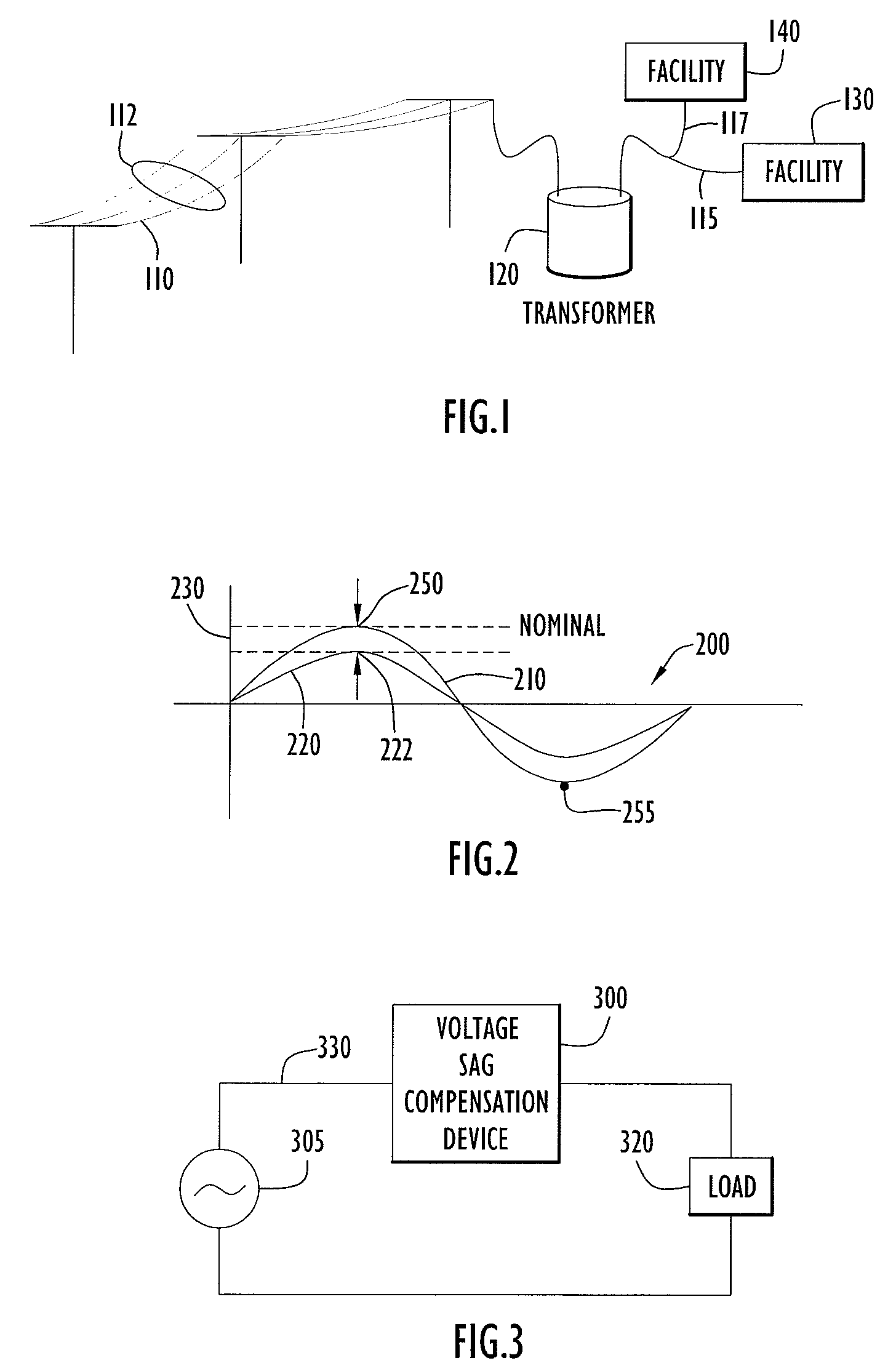
[0033]FIG. 1 is a schematic diagram of a basic power system 100 in which the present invention may be utilized. As shown, a utility power line 110, or a collection of power lines 112 for 3-phase power, is strung near a facility 130. A stepdown transformer 120 may be connected between the power line 110 and power line 115 that services facility 130 such that facility 130 is provided electrical power at an appropriate voltage level, e.g. 120V. Facility 130 may include electric machinery, relays, heaters, and control systems that receive power via power line 115. At the same time, another facility 140 (perhaps with similar types of electrical loads) may also be receiving electrical power from power line 110 via power line 117. Due to the periodic switching in and out of selected loads at either or both facilities 130, 140, as well as possible faulty wiring, unexpected short circuits, and the like, there may be instantaneous changes in the amount of electrical current that is drawn from...


PUM


Abstract

A voltage sag compensation system includes a capacitor charging and discharging module connected to an AC rectifier and to an inverter, a two stage voltage detector configured to detect a degree of voltage sag that is present on a power line, and an inverter gating module selectively connectable to the power line in response to the two stage voltage detector and configured to provide gating signals to the inverter. The system further includes a low DC bus switch out module configured to monitor an output voltage of the capacitor charging and discharging module and to disable the inverter gating module from providing the gating signals to the inverter when voltage associated with the capacitor charging and discharging module falls below a predetermined value.

Description

FIELD OF THE INVENTION[0001]The present invention is related to electrical power systems, and more particularly to systems and methods for compensating for momentary voltage sag or dip on an electric power line.BACKGROUND OF THE INVENTION[0002]AC power systems, as is well-known in the art, provide electric power in the form of voltage and current that alternate between positive and negative polarities, typically following a sine wave with a predetermined amplitude and frequency. In the U.S., nominal amplitude is 120 volts RMS, at a frequency of 60 Hz. There are many types of electrical equipment, such as motors and relays that depend on quality power supply conditions to operate properly. More specifically, it is often critical that peak line voltage actually attain the expected nominal peak voltage to avoid, e.g., undesirable motor vibration or inadvertent relay switching, among other possible impacts of power line voltage fluctuations or transients.[0003]When line voltage does not...

Claims


Application Information

Patent Timeline
Patent Type & Authority Patents(United States)
IPC IPC(8): H02J1/00
CPCH02J3/12H02J3/1842Y02E40/22Y02E40/20
Inventor DAWLEY, ROBERT ALBERT
Owner ELECTRONICS SYST PROTECTION
Why Eureka
Try Eureka