DMD comprising nonparallel mirror deflection axes

a technology of deflection axes and mirrors, applied in the field of digital mirror devices, can solve the problems of bulky and expensive structure of tpa

Inactive Publication Date: 2009-06-02
MAYER MAX +1
View PDF6 Cites 9 Cited by
  • Summary
  • Abstract
  • Description
  • Claims
  • Application Information

AI Technical Summary

Benefits of technology

[0009]In this invention, we uncover a single DMD-chip that has different classes of mirrors. While the mirrors of a single class are deflected on parallel MDAs, the classes differ by the specific orientation of their

Problems solved by technology

Due to the stereo-isomeric characteristics, an even-numbered difference of the reflecti

Method used


Image

  • DMD comprising nonparallel mirror deflection axes
  • DMD comprising nonparallel mirror deflection axes
  • DMD comprising nonparallel mirror deflection axes

Examples


Embodiment Construction

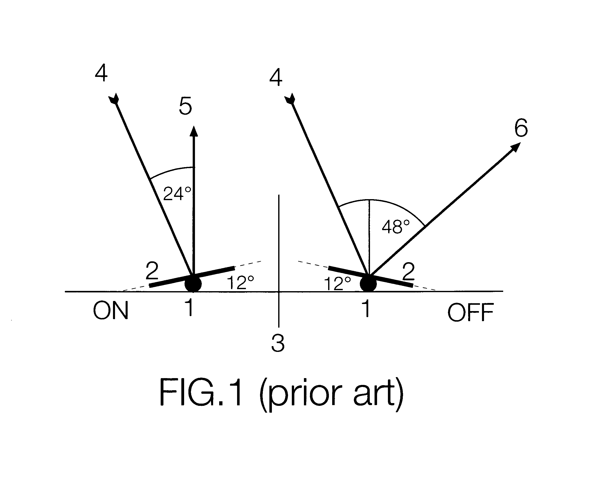
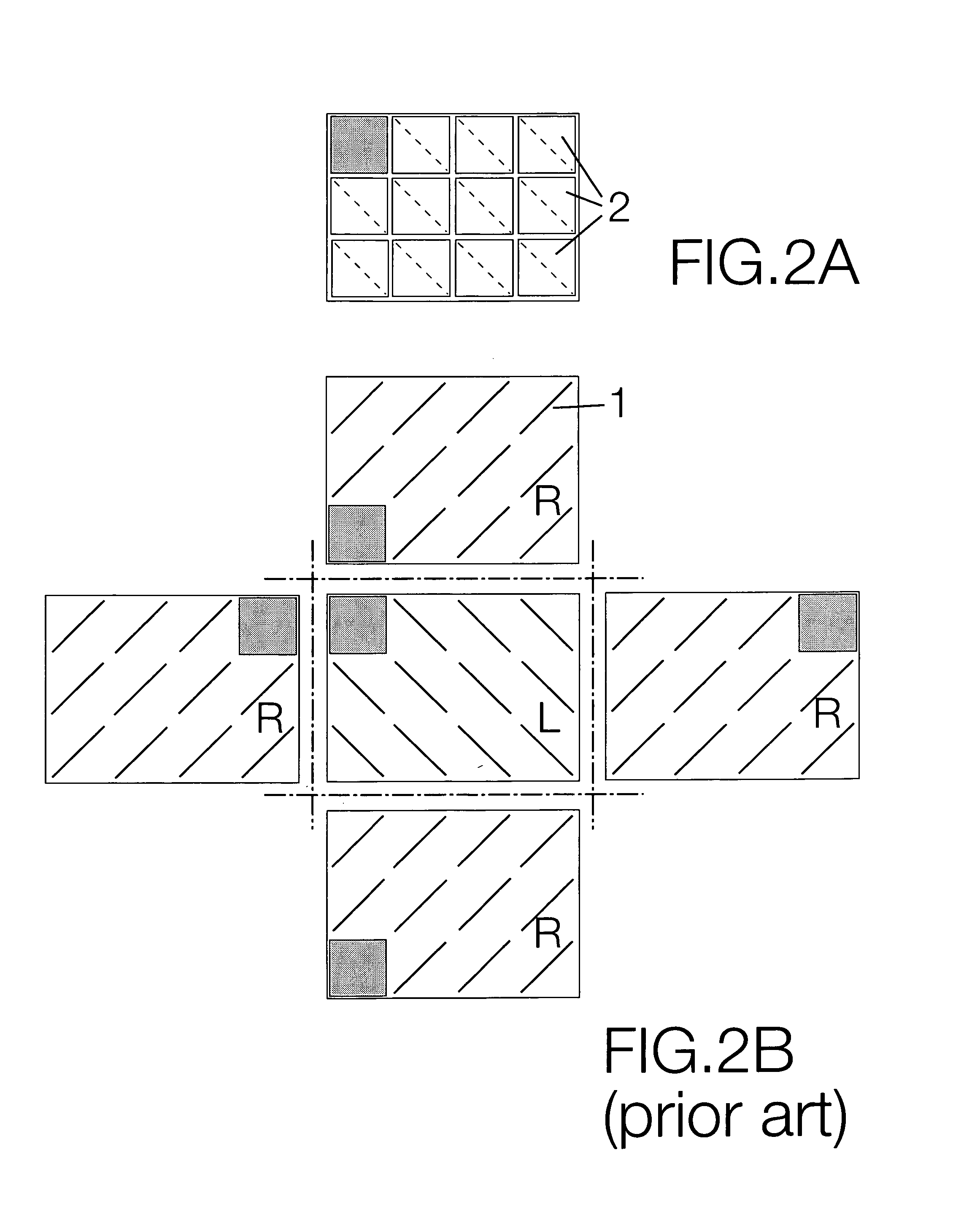
[0014]The figures are labeled in a way that identical numbers indicate identical components in all figures. Mirror deflection axis (1); single deflectable mirror (2); normal (3); incident beam (4); “On”-beam (5); “Off”-beam (6);

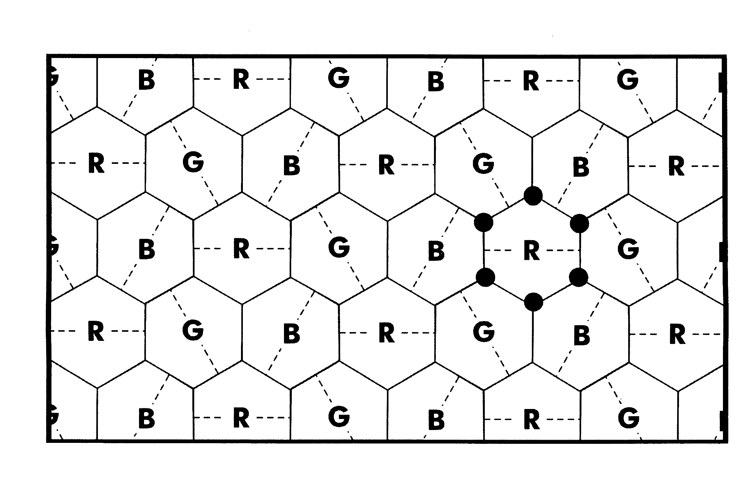
[0015]FIG. 3 shows schematic views of examplary arrangements of single mirrors of a DMD with three classes of mirrors with the classes having a different orientation of MDAs. In general, the three classes of mirrors will be homogeneoulsy distributed on the DMD surface. This can generally be reallized by various geometric solutions. FIGS. 3A-D show two geometric solutions of an homogenous distribution of mirrors belonging to three classes, which have orientations of the MDAs with cutting angles of 120 deg. (This is the largest angle difference for a system with three classes).

[0016]FIGS. 3C and 3D show two space-filling arrangements of mirrors. In FIG. 3C, the mirrors have rhomb-shapes and completely fill the chip surface. In FIG. 3D hexagonal mirrors are arra...


PUM


Abstract

The digital mirror device (DMD) is an array of single mirrors, which are deflectable on mirror deflection axes (MDAs, as e.g. characterized by their orientation with the array raster). In the state of the art, all single mirrors on a DMD have parallel MDAs. In our invention, the array is made of different classes of mirrors. These classes differ by the orientation of their MDAs. The invention relates to the simultaneous processing of different characteristics of light (e.g. color) by a single DMD-chip.

Description

CROSS-REFERENCE TO RELATED APPLICATIONS[0001]Not applicableSTATEMENT REGARDING FEDERALLY SPONSORED RESEARCH OR DEVELOPMENT[0002]Not applicableREFERENCE TO SEQUENCE LISTING, A TABLE, OR A COMPUTER PROGRAM LISTING COMPACT DISK APPENDIX[0003]Not applicableBACKGROUND OF THE INVENTION[0004]The present invention uncovers a digital mirror device (DMD), which comprises an array of single deflectable mirrors with nonparallel axes of deflection. The invention relates to simultaneous processing of different light characteristics, e.g. spectral or polarization specifics, by a single DMD-chip.[0005]The DMD according to the state of the art (Texas Instruments, Hornbeck 1997, U.S. Pat. No. 5,600,383) is made of an isomorphic array of single deflectable mirrors. Moreover, all mirrors are identical with regards to all aspects but their relative position (and address) in the array raster. The mirror deflection axes (MDA) of all single mirrors are parallel in the recent DMD. This is a consequence of f...

Claims


Application Information

Patent Timeline
IPC IPC(8): G02B26/00G02B26/08
CPCG02B26/0833
Inventor MAYER, MAXBAUSENWEIN, BERNHARD RUDOLF
Owner MAYER MAX
Why Eureka
Try Eureka