Cooling tower fan locking apparatus

a technology of locking apparatus and cooling tower, which is applied in the direction of mechanical equipment, machines/engines, sustainable buildings, etc., can solve the problems of cooling water, drive shaft, damage to the cooling tower, etc., and achieve the effect of easy engagement, and preventing uncontrolled rotation of the fan

Active Publication Date: 2009-06-09
COOLING TOWERS OF TEXAS
View PDF4 Cites 0 Cited by
  • Summary
  • Abstract
  • Description
  • Claims
  • Application Information

AI Technical Summary

Benefits of technology

[0007]The cooling tower fan locking apparatus of the invention overcomes the above discussed disadvantages of existing cooling tower fan constructions by providing a locking or braking apparatus on the drive shaft that prevents uncontrolled rotation of the fan due to high wind conditions in the atmosphere. The locking apparatus of the invention is designed to be positioned around the drive shaft coupling of an existing cooling tower. When high wind conditions are forecast in the area of the cooling tower fan, the locking apparatus can be easily engaged to lock the drive shaft stationary relative to the cooling tower and prevent uncontrolled rotation of the fan in the high wind conditions.
[0010]The two lock members have the same basic construction and are substantially mirror images of each other. With the constructions of the first and second lock members being similar, their manufacturing costs are reduced.
[0022]In this manner, the fan shaft is braked by the fan locking apparatus of the invention, and high wind conditions in the atmosphere of the cooling tower are prevented from rotating the fan.

Problems solved by technology

The surfaces spread the heated water, exposing the water to the atmosphere which results in cooling of the water.
This open construction exposes the fan in the tower to high winds.
Due to the rotating speed of the fan, the impact can shatter the fan, damage the reduction gearing and the drive shaft of the fan, and damage the cooling tower fan stack surrounding the fan, making the fan stack more susceptible to being torn from the cooling tower on the roof top of a building or in the open area of a refinery, petrochemical facility, power plant, etc., by the high force winds.

Method used


Image

  • Cooling tower fan locking apparatus
  • Cooling tower fan locking apparatus
  • Cooling tower fan locking apparatus

Examples


Embodiment Construction

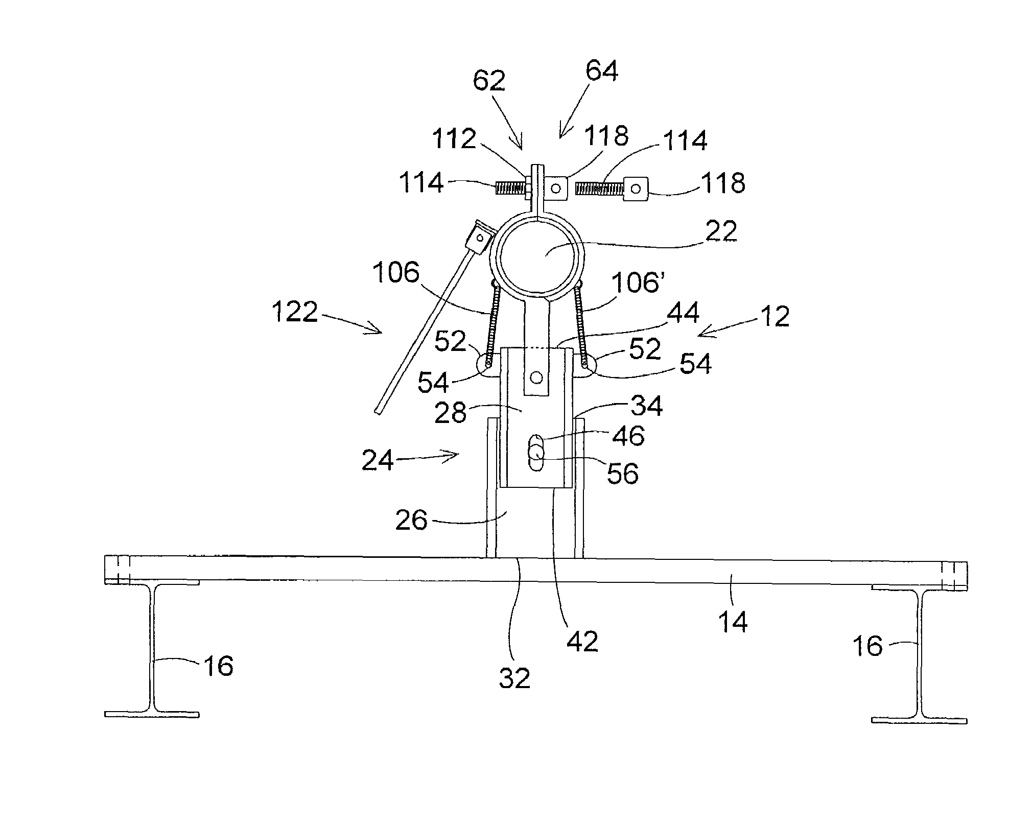
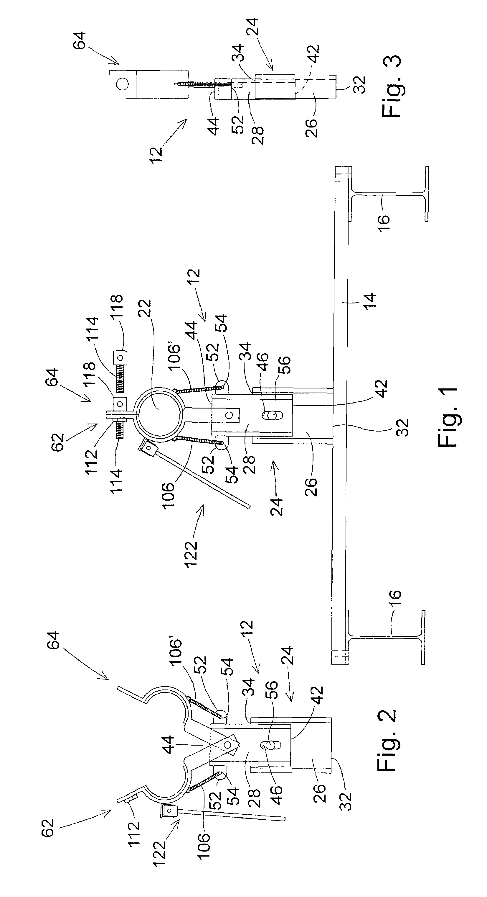
[0037]The cooling tower fan locking apparatus of the invention is designed to hold the fan shaft of a cooling tower fan against free rotation due to high wind conditions in the atmosphere. The apparatus of the invention is designed to be secured to an existing stationary structure of a cooling tower adjacent to the fan shaft of the cooling tower. What is meant by “fan shaft” is any shaft of the cooling tower assembly that is rotated by a motive source of the cooling tower and is operatively connected to a fan of the cooling tower to rotate the fan. FIGS. 1 and 12 of the drawing figures show the apparatus 12 of the invention secured to examples of stationary structures of a cooling tower. In the preferred embodiment of the apparatus 12, all of the apparatus component parts are stainless steel. FIG. 1 shows a stainless steel channel 14 that is employed to operatively connect the apparatus 12 to stationary structures 16 of a cooling tower, for example unitized supports 16 of the coolin...


PUM


Abstract

A mechanical locking apparatus is assembled to an existing cooling tower fan assembly and is operable to brake the drive shaft of the fan assembly to stop rotation of the fan and isolate the fan from rotating in high winds.

Description

[0001]This patent application claims the benefit of provisional patent application No. 60 / 812,818, filed Jun. 12, 2006.BACKGROUND OF THE INVENTION[0002](1) Field of the Invention[0003]The present invention pertains to a mechanical locking apparatus that is assembled to an existing cooling tower fan assembly and is operable to brake the drive shaft of the fan assembly, keeping the fan from rotating in high winds.[0004](2) Description of the Related Art[0005]A cooling tower is a structure that is used to cool a liquid, typically water, that is heated by the operation of an air conditioning system of a large building, a refinery, a petrochemical facility, a manufacturing facility, an electric power generation facility, or other similar facility. The cooling tower is typically constructed on the top of a building or other similar structure, or in an open area of a refinery, petrochemical facility, power generation facility, etc. where it is directly exposed to the atmosphere. The heated...

Claims


Application Information

Patent Timeline
Patent Type & Authority Patents(United States)
IPC IPC(8): F03D7/02
CPCF03D7/0248F05B2260/902Y02B10/30Y02E10/723Y02E10/72
Inventor DANIEL, SHAWN E.
Owner COOLING TOWERS OF TEXAS
Why Eureka
Try Eureka