Optical Magnification System

a technology of optical magnification and magnification chamber, which is applied in the direction of mountings, instruments, camera body details, etc., can solve the problems of increased manufacturing cost, irregular jittering of user's view through the lens unit, and high manufacturing accuracy, so as to avoid uncontrolled rotation, shaking or jittering

Inactive Publication Date: 2018-07-19
SINTAI OPTICAL SHENZHEN CO LTD +1
View PDF1 Cites 1 Cited by
  • Summary
  • Abstract
  • Description
  • Claims
  • Application Information

AI Technical Summary

Benefits of technology

[0005]The invention provides an optical magnification system. The lens seat of the optical magnification system is constrained within the inner lens barrel to avoid uncontrolled rotation, shaking or jittering of the lens seat relative to the inner lens barrel. As a result, the lens seat can be moved stably in an axial direction of the inner lens barrel relative to the inner lens barrel.

Problems solved by technology

If a clearance between the lens seat and the inner lens barrel is undue, user's view through the lens unit may irregularly jitter relative to the reticle of the sight.
However, that requires higher manufacturing accuracy and therefore increases the manufacturing cost.

Method used


Image

  • Optical Magnification System
  • Optical Magnification System
  • Optical Magnification System

Examples


Embodiment Construction

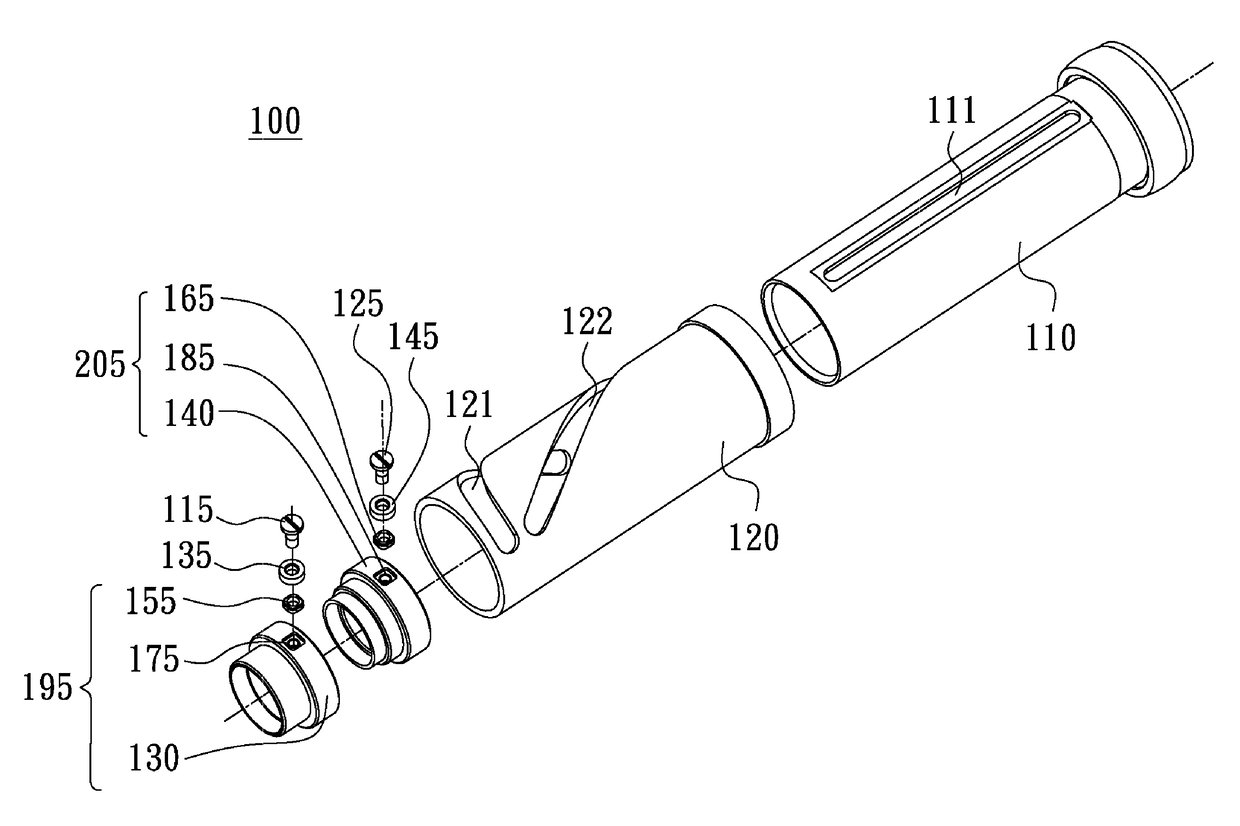
[0031]Referring to FIG. 4, an optical magnification system 100 in accordance with a first embodiment of the invention includes a first lens barrel 110, a second lens barrel 120, a first lens seat 195, a second lens seat 205, a first lens unit (not shown) and a second lens unit (not shown). The second lens barrel 120 is configured to move the first lens seat 195 and the second lens seat 205 relative to the first lens barrel 110, so as to adjust magnification of the optical magnification system 100.

[0032]As shown in FIG. 4, the second lens barrel 120 is rotatably disposed around the first lens barrel 110 and includes a first slot 121 and a second slot 122 respectively formed thereon. The first lens barrel includes a slot 111 formed thereon. In the first embodiment, the first slot 121 and the second slot 122 are curved with different curvatures. The slot 111 extends parallel to an axis of the first lens barrel 110.

[0033]The first lens unit and the second lens unit are respectively disp...


PUM


Abstract

An optical magnification system includes a lens barrel, a lens seat, a bush and a fixing element. The lens barrel has a slot. The lens seat includes a seat body and a sliding portion, wherein the seat body is movably disposed within the lens barrel, and the sliding portion is disposed on the seat body, extends into the slot and is configured to slide within the slot. The bush is movably disposed on the lens barrel. The fixing element extends through the bush and the sliding portion and is fixed to the seat body. The lens seat is configured to move relative to the lens barrel and along the slot via the sliding portion. The lens seat and the bush are respectively forced against the inner circumferential surfaces and the outer circumferential surfaces of the lens barrel by the fixing element.

Description

BACKGROUND OF THE INVENTIONField of the Invention[0001]The invention relates to an optical magnification system, and more particularly to an optical magnification system with the directional stability of a lens seat improved.Description of the Related Art[0002]A conventional sight is generally provided with an optical magnification system 1 which, as shown in FIGS. 1-3, includes an outer lens barrel 20, an inner lens barrel 10, a first lens seat 30, a second lens seat 40, a first screw 15, a second screw 25, a first bush 35 and a second bush 45. The outer lens barrel 20 is rotatably disposed around the inner lens barrel 10 and has a first curved slot 21 and a second curved slot 22 respectively formed thereon. The inner lens barrel 10 has a straight slot 11 formed thereon and the straight slot extends parallel to an axis of the inner lens barrel 10. A first lens unit (not shown) and a second lens unit (not shown) are respectively fixed within the first lens seat 30 and the second len...

Claims


Application Information

Patent Timeline
Patent Type & Authority Applications(United States)
IPC IPC(8): G02B15/16G02B7/04G02B7/10
CPCG02B15/161G02B7/04G02B7/10G02B15/142G03B17/12
Inventor CHANG, CHIA-KAN
Owner SINTAI OPTICAL SHENZHEN CO LTD
Why Eureka
Try Eureka