Electric connector

a technology of electric connectors and connectors, applied in the direction of electrical apparatus, coupling device connections, incorrect coupling prevention, etc., can solve the problems of apprehensive feelings in workers, objects could strike against, break or otherwise damage the cpa, and achieve the effect of smooth pushing outward

Inactive Publication Date: 2009-06-09
MEA TECH PTE
View PDF8 Cites 50 Cited by
  • Summary
  • Abstract
  • Description
  • Claims
  • Application Information

AI Technical Summary

Benefits of technology

[0010]An advantage of some aspects of the present invention is to provide an electric connector that has a mating sensing member able to sense the mating status of a pair of connectors during mating thereof.
[0011]Another advantage of some aspects of the present invention is to provide an electric connector wherein the mating sensing member is formed as a single part, thereby reducing the cost, and moreover can be installed to the housing with ease.
[0012]Further another advantage of some aspects of the present invention is to provide an electric connector that is rendered compact.

Problems solved by technology

However, it sometimes happens that while the two connectors are being mated together and are in, say, a semi-mated state, their contact terminals become electrically connected to each other, in which case the two connectors will be joined without being locked, and therefore may come apart accidentally during use.
However, with these electric connectors, it is not possible to sense the mating status of the first and second connectors during the mating process thereof, which means that if it is determined via pushing-in of the CPA that the two connectors are in a semi-mated state, then it will be necessary to perform over again both the mating manipulation of the connectors and the installation of the CPA.
Such manipulations may cause apprehensive feelings in the worker.
Further, with the electric connector disclosed in EU Patent Application EP0840398A1, the CPA is exposed when installed to the connector housing, which means that objects could strike against and break or otherwise damage the CPA.

Method used


Image

  • Electric connector
  • Electric connector
  • Electric connector

Examples


Embodiment Construction

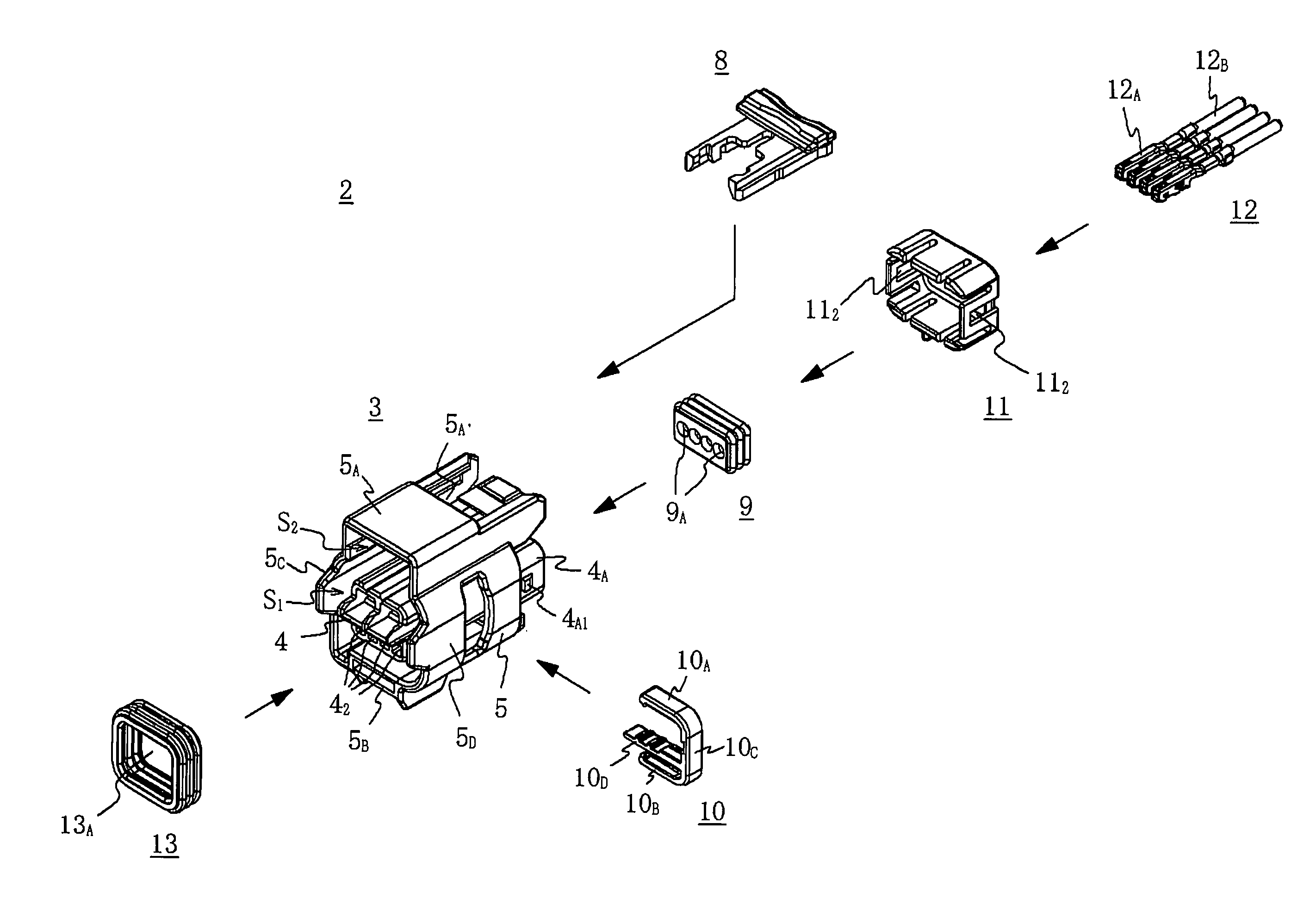
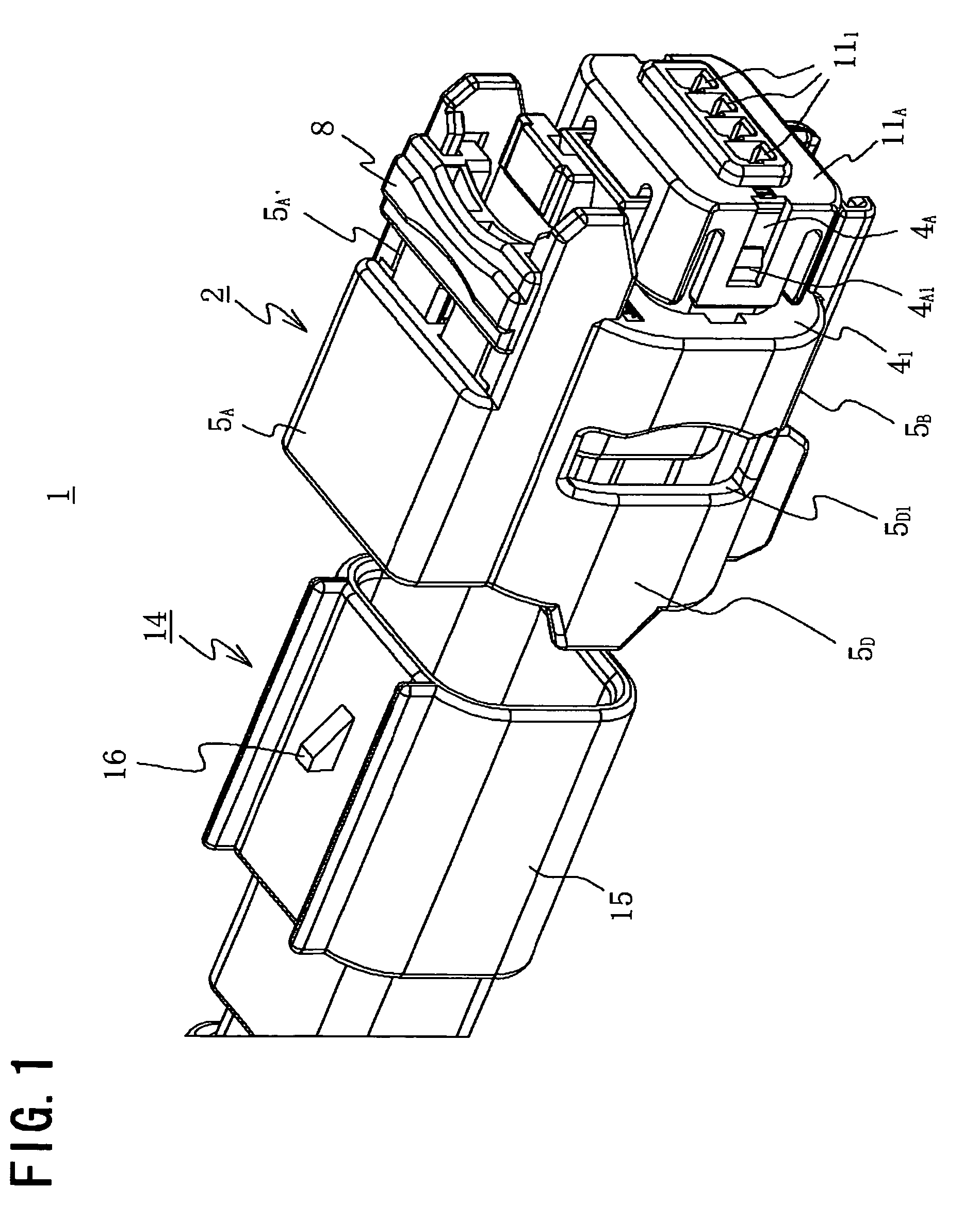
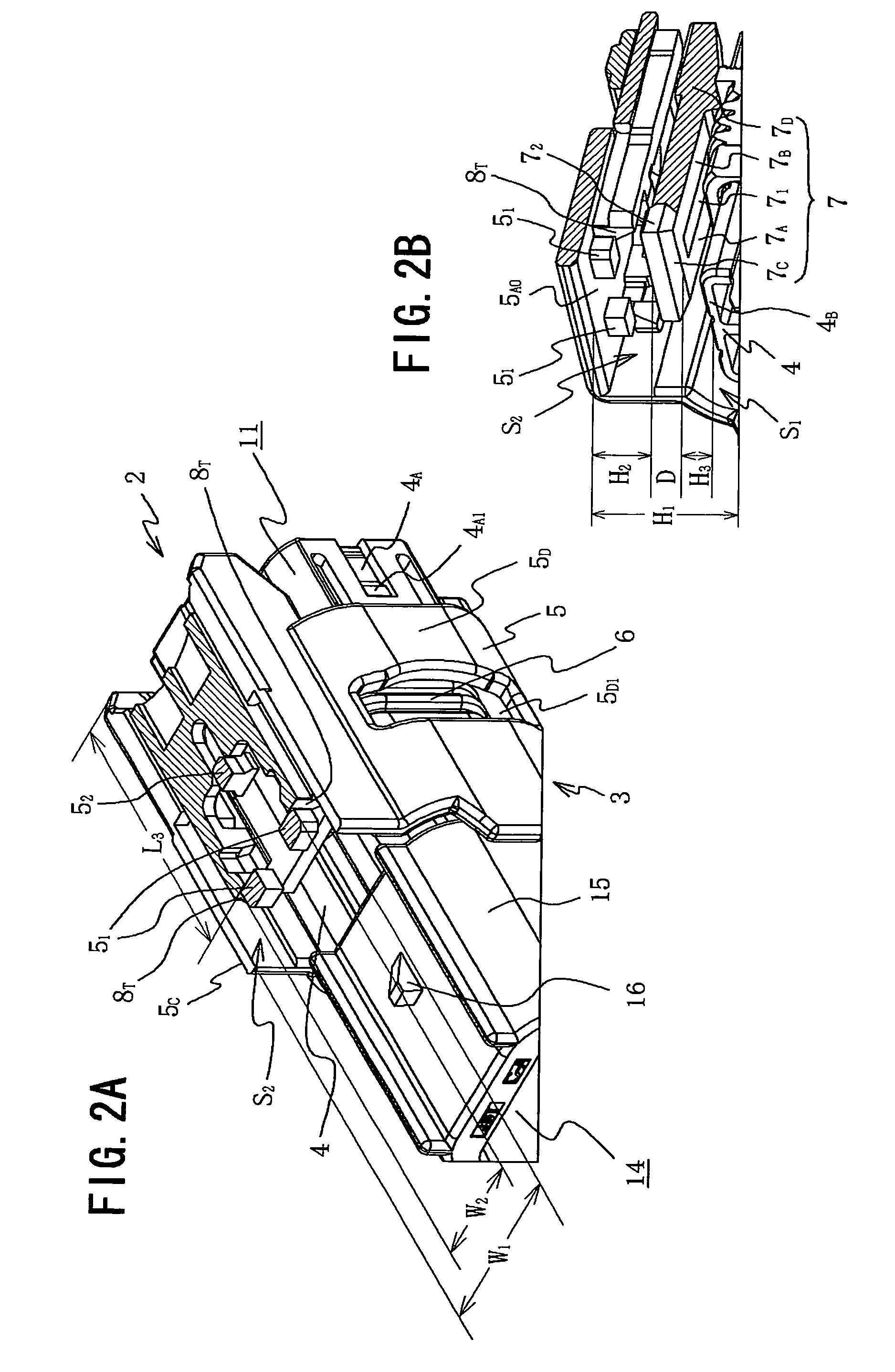
[0034]An exemplary embodiment of the present invention will now be described with reference to the accompanying drawings. It will be understood however, that the following embodiment is intended merely by way of an illustrative example of an electric connector that realizes the technical concepts of the invention, not by way of limiting the invention to this particular electric connector. The invention can equally well be adapted to yield other embodiments within the scope and spirit of the claims. FIG. 1 is a perspective view of an electric connector of an embodiment of the invention, FIG. 2A is a perspective view of the female connector housing in FIG. 1 with part of the outer wall thereof cut away, FIG. 2B is a perspective view of the interior of the housing cut-away portion in FIG. 2A, and FIG. 3 is an exploded perspective view of the female connector in FIG. 1.

[0035]As FIGS. 1 and 3 show, an electric connector 1 includes a female connector 2 (second connector) having a female c...


PUM


Abstract

The second connector 2 has an inner housing 4 and an outer housing 5 that covers the outer peripheries of the inner housing 4, forming a gap S1 for insertion of the first connector 14 therebetween. A receiving cavity S2 is provided for insertion of the mating sensing member 8, and inside which is provided a pair of first stopper projections 51, a second stopper projections 52 and an elastically deformable locking arm 7, front end of which is a free extremity. The locking arm 7 is provides at the front end portion 7C with a pushing portion 72 and a first stopper 74 on each of the two sides. The mating sensing member 8 has a pair of elastically deformable first and second fingers 8A, 8B positioned opposing each other in parallel and they have an actuation portion 80 and a stopper engaging portion 8D.

Description

TECHNICAL FIELD[0001]The present invention relates to an electric connector composed of a male connector and a female connector, and more particularly to an electric connector that has means for sensing the mating status of the two connectors.BACKGROUND ART[0002]Electric connectors composed of a male and a female connector usually have a locking means that prevents the two connectors from coming apart accidentally in the joined state. However, it sometimes happens that while the two connectors are being mated together and are in, say, a semi-mated state, their contact terminals become electrically connected to each other, in which case the two connectors will be joined without being locked, and therefore may come apart accidentally during use. Accordingly, electric connectors are known which have a mating sensing means that is able to sense the mating status in order to prevent such joining in a semi-mated state.[0003]For instance, an electric connector 25 disclosed in U.S. Pat. No....

Claims


Application Information

Patent Timeline
Patent Type & Authority Patents(United States)
IPC IPC(8): H01R13/627
CPCH01R13/4361H01R13/4367H01R13/5208H01R13/6272H01R13/641H01R13/7032H01R13/639H01R13/64
Inventor LIM, CHEE BOON VINCENT
Owner MEA TECH PTE
Why Eureka
Try Eureka