Speaker, module using the same, electronic equipment and device, and speaker producing method

a technology of speaker and module, applied in the direction of electromechanical transducers, transducer diaphragms, instruments, etc., can solve the problems of deteriorating performance of the speaker, and achieve the effect of not reducing the size of the permanent magnet and the edg

Inactive Publication Date: 2009-06-16
PANASONIC CORP
View PDF20 Cites 12 Cited by
  • Summary
  • Abstract
  • Description
  • Claims
  • Application Information

AI Technical Summary

Benefits of technology

[0005]A speaker of the present invention includes: a magnet circuit assembly including a frame and a permanent magnet; a diaphragm assembly including a diaphragm, and a voice coil attached to the outer periphery of the diaphragm; and an edge that is attached to the frame along the outer periphery thereof and joined onto the diaphragm in a position more peripherally inward than the voice coil along the inner periphery thereof to partly overlap the diaphragm, and that supports the diaphragm assembly with respect to the frame. The edge partly overlaps the diaphragm. This structure allows the speaker to be downsized, without reducing the sizes of the permanent magnet and edge.

Problems solved by technology

The problem with the above speaker is that its performance is deteriorated when the speaker is downsized to meet market requests, because the size of diaphragm 7, edge 9, or permanent magnet 1 must be reduced.

Method used


Image

  • Speaker, module using the same, electronic equipment and device, and speaker producing method
  • Speaker, module using the same, electronic equipment and device, and speaker producing method
  • Speaker, module using the same, electronic equipment and device, and speaker producing method

Examples


first exemplary embodiment

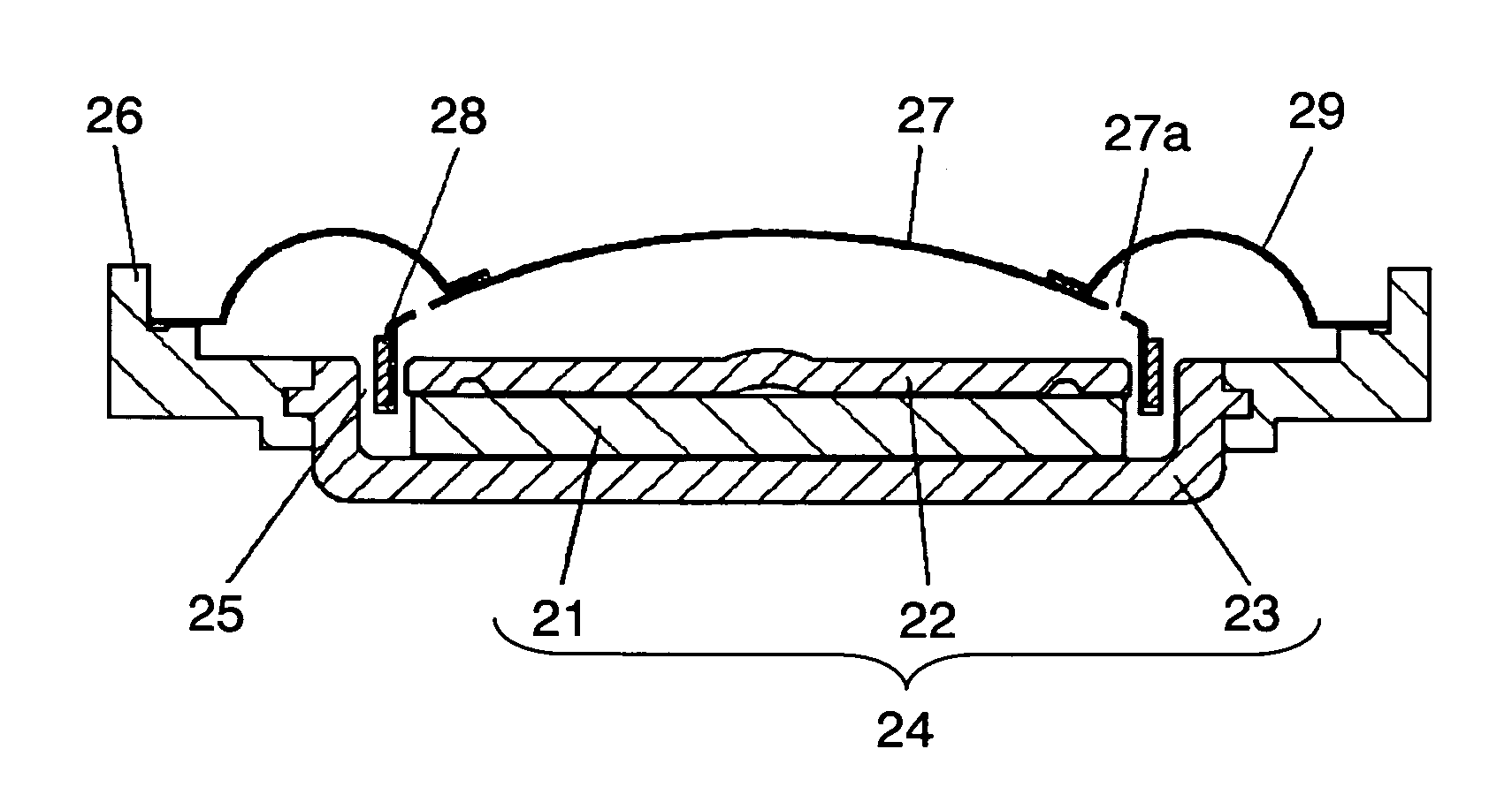
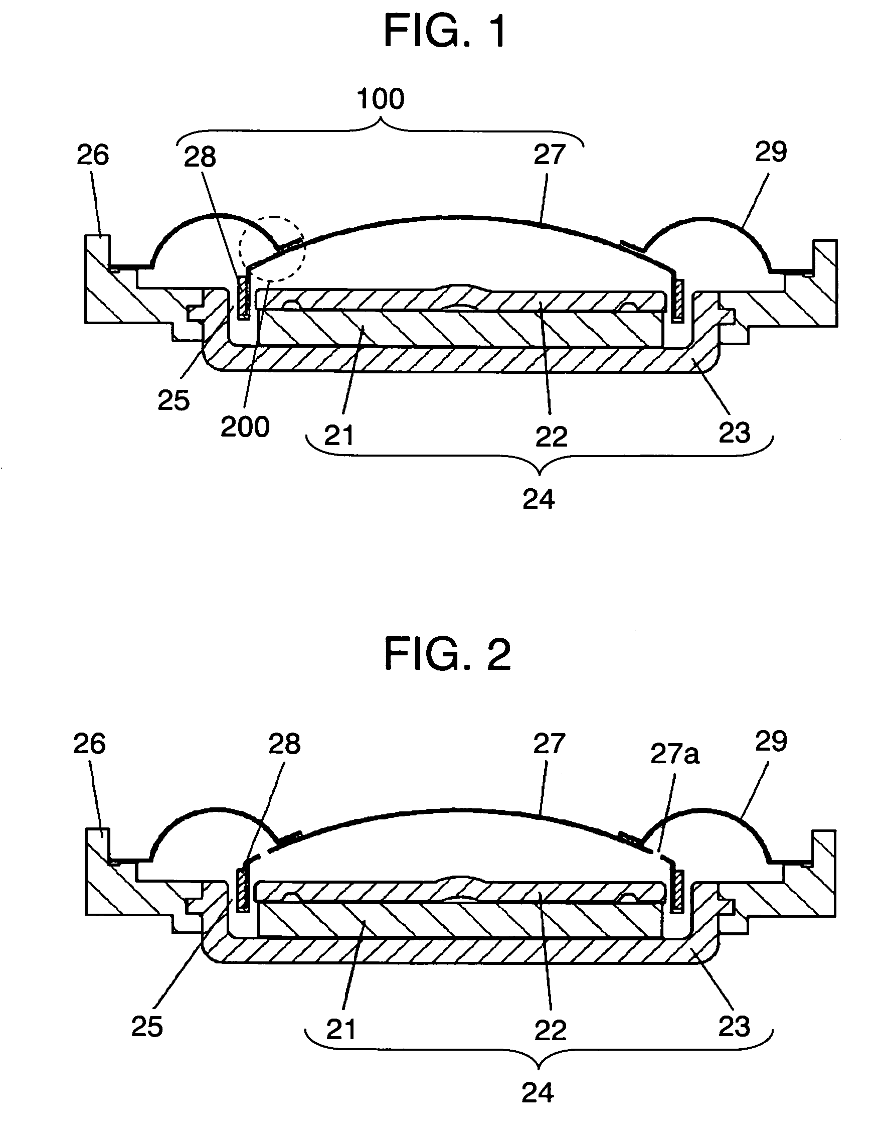
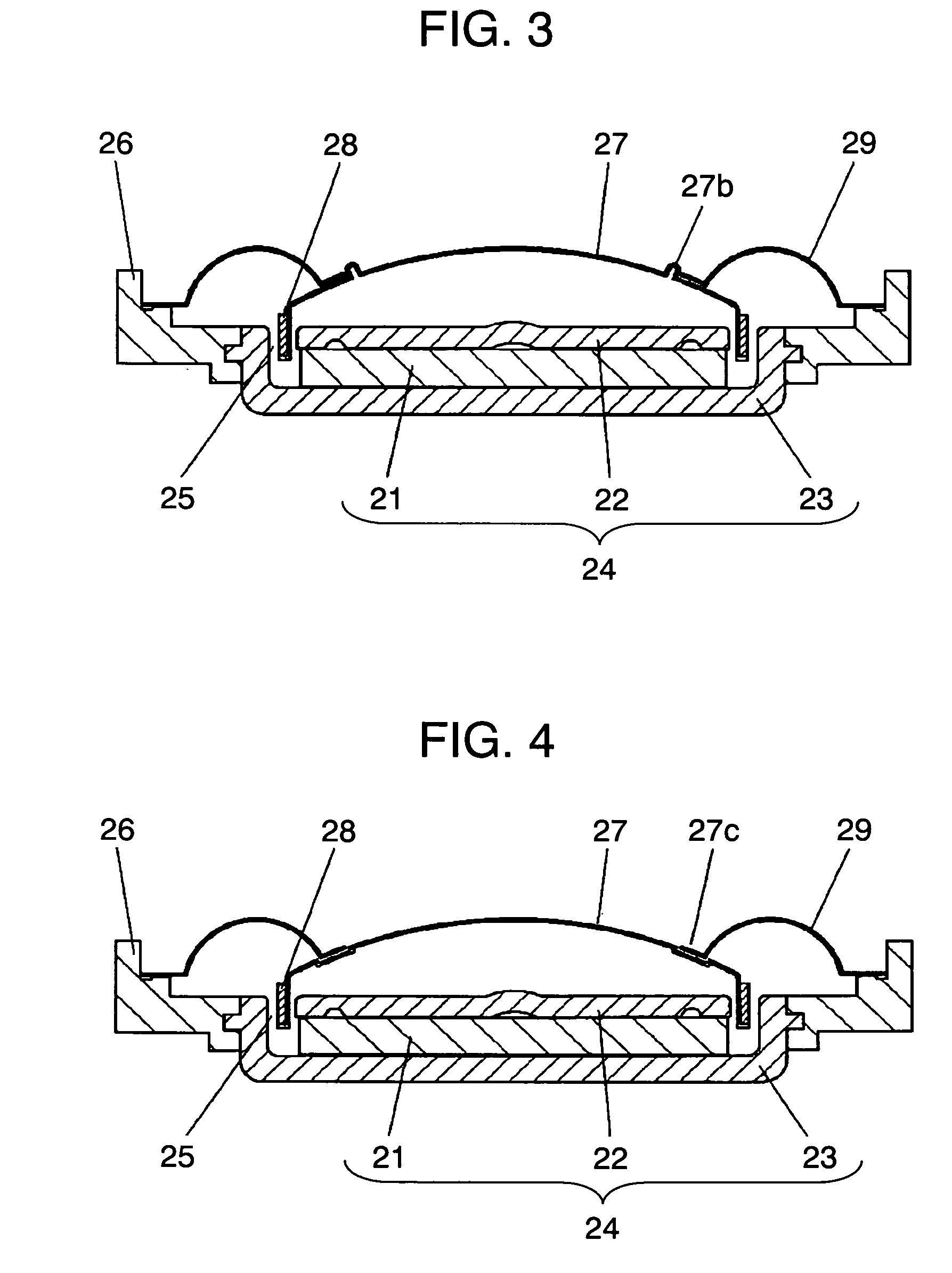
[0028]FIG. 1 is a sectional view of a speaker in accordance with the first exemplary embodiment of the present invention. Permanent magnet 21 is sandwiched between upper plate 22 and yoke 23 to form magnetic circuit assembly 24. Frame 26 is fitted to yoke 23. Diaphragm 27 and voice coil 28 attached to the outer periphery of diaphragm 27 form diaphragm assembly 100. Edge 29 supports diaphragm assembly 100 with respect to frame 26 so that voice coil 28 is placed in magnetic gap 25 in magnetic circuit assembly 24. Edge 29 is bonded to frame 26 along the outer periphery thereof, and joined to diaphragm 27 in a position more peripherally inward than voice coil 28 along the inner periphery thereof. Therefore, edge 29 partly overlaps diaphragm 27.

[0029]Now, the portion in which edge 29 overlaps diaphragm 27 is referred to as crossover portion 200. Crossover portion 200 is structured so that a portion in which edge 29 overlaps diaphragm 27 is ensured, other than the bonding portion, i.e. a ...

example 1

[0032]When a material thinner than that of diaphragm 27 is used for edge 29, hard and thicker diaphragm 27 reproduces high tones with high fidelity while expanding the higher limit frequency thereof. Thinner edge 29 allows voice coil 28 and diaphragm 27 to easily vibrate, lower the F0 of the speaker, and thus reproduce low tones with high fidelity.

example 2

[0033]When a material softer than that of diaphragm 27 is used for edge 29, harder diaphragm 27 reproduces high tones with high fidelity while expanding the higher limit frequency thereof. Softer edge 29 allows voice coil 28 and diaphragm 27 to easily vibrate, lower the F0 of the speaker, and thus reproduce low tones with high fidelity.


PUM

PropertyMeasurementUnit
thicknessaaaaaaaaaa
sizeaaaaaaaaaa
sizesaaaaaaaaaa

Abstract

An edge (29) for supporting a diaphragm assembly (100) with respect to a frame (26) is bonded to the frame (26) along the outer periphery thereof and joined to a diaphragm (27) in a position more peripherally inward than a voice coil (28) along the inner periphery thereof. The edge (29) partly overlaps diaphragm (27). This structure allows downsizing of the speaker, without reducing the sizes of a permanent magnet (21) and the edge (29).

Description

[0001]This application is a U.S. national phase application of PCT International Application PCT / JP2005 / 004763, filed Mar. 17, 2005.TECHNICAL FIELD[0002]The present invention relates to a speaker, a device using the speaker, and a method of manufacturing the speaker.BACKGROUND ART[0003]FIG. 16 is a sectional view of a conventional speaker disclosed in Unexamined Japanese Utility Model Publication No. 57-111196. Permanent magnet 1 is sandwiched between upper plate 2 and yoke 3 to form magnetic circuit assembly 4. Frame 6 is fitted to yoke 3. The outer periphery of edge 9 is attached onto frame 6. Voice coil 8 attached to diaphragm 7 is placed in magnetic gap 5 in magnetic circuit assembly 4. Diaphragm 7 and edge 9 along the outer periphery of diaphragm 7 are unitarily formed of one resin film sheet.[0004]The problem with the above speaker is that its performance is deteriorated when the speaker is downsized to meet market requests, because the size of diaphragm 7, edge 9, or permanen...

Claims


Application Information

Patent Timeline
Patent Type & Authority Patents(United States)
IPC IPC(8): H04R1/00H04R11/02H04R9/06H04R7/18H04R7/24H04R7/26H04R9/04H04R31/00
CPCH04R7/24H04R31/006H04R7/16Y10T29/49002Y10T29/4908Y10T29/49005H04R9/04H04R31/00H04R7/02H04R7/26
Inventor FUKUYAMA, TAKANORITAKASE, TOMOYASUSANO, KOJIYANO, HIROSHINAKANO, MASANORITOMOEDA, SHIGERUHONDA, KAZUKIYAMASAKI, KAZUYAKUBO, KAZUTAKASHIMOKAWATOKO, TAKESHIENOMOTO, MITSUTAKASUMIYAMA, MASAHIDE
Owner PANASONIC CORP
Why Eureka
Try Eureka