Image capturing apparatus and method for controlling the image capturing apparatus
a technology of image capturing apparatus and image capturing apparatus, which is applied in the direction of color television details, television systems, radio control devices, etc., can solve the problems of reducing the size of the photodiode portion serving as a photoelectric conversion unit, and reducing the sensitivity, so as to achieve a wide dynamic range and reduce the size of the photodiode portion
- Summary
- Abstract
- Description
- Claims
- Application Information
AI Technical Summary
Benefits of technology
Problems solved by technology
Method used
Image
Examples
first embodiment
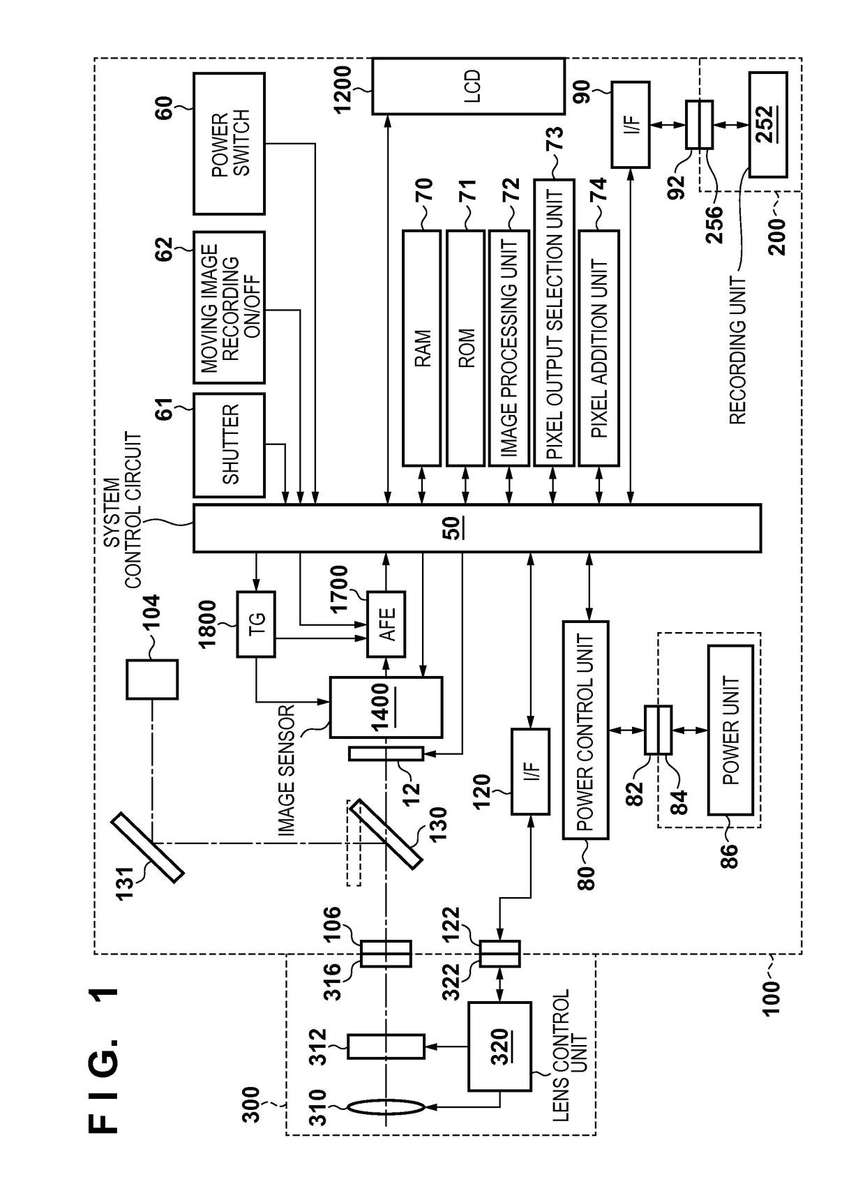
[0043]FIG. 1 is a block diagram showing a configuration of an image capturing apparatus according to a first embodiment of the present invention. The image capturing apparatus mainly includes an image processing apparatus 100, a recording medium 200 such as a memory card or a hard disk, and a lens unit 300.
[0044]The lens unit 300 includes a taking lens 310, an aperture 312, a lens mount 316, a lens control unit 320, and a connector 322. The lens mount 316 mechanically connects the lens unit 300 to a lens mount 106 of the image processing apparatus 100. The connector 322 is electrically connected to the image processing apparatus 100 via a connector 122 on the image processing apparatus 100 side. The lens control unit 320 receives a signal from the image processing apparatus 100 via the connectors 322 and the 122, and performs focus adjustment by changing the position of the taking lens 310 on the optical axis in accordance with the received signal. The lens control unit 320 receives...
second embodiment
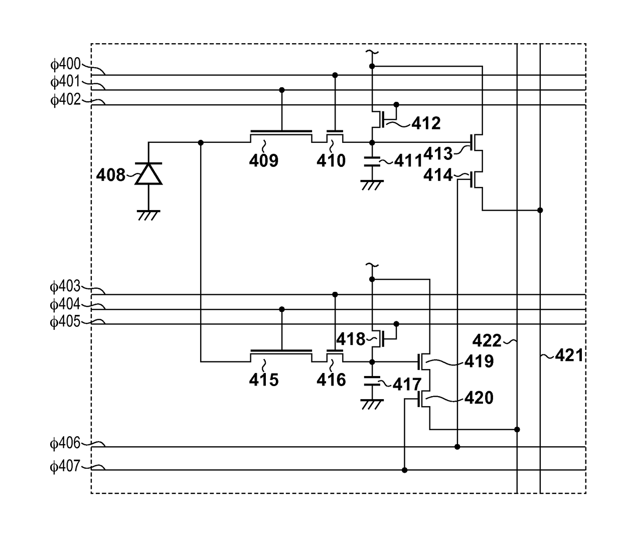
[0086]Next, a second embodiment of the present invention will be described. Note that the configurations of the image capturing apparatus and the image sensor according to the second embodiment are the same as those described with reference to FIGS. 1 to 4B in the first embodiment described above, and therefore, the description thereof shall be omitted here. In the second embodiment, each of the CCDs 409 and 415 is driven at the same timing such that the charge accumulation period is the same, and whether to add or independently output the two outputs in a later stage is selected.
[0087]With reference to FIGS. 11 and 12, a description will be given of charge transfer by a readout scheme according to the second embodiment. FIG. 11 shows a timing chart of control signals according to the second embodiment. FIG. 12 shows a potential transition diagram according to the second embodiment. Note that the control of the control signals φ400 to φ407 shown in FIG. 11 is performed by the CPU 50...
third embodiment
[0100]Next, a third embodiment of the present invention will be described. Note that the configurations of the image capturing apparatus and the image sensor according to the third embodiment are different in the configuration of the image sensor 1400 from those described with reference to FIGS. 1 to 4B in the first embodiment described above. The rest of the configurations are the same, and therefore, the description thereof shall be omitted here. Additionally, in the third embodiment, as with the second embodiment, each of the CCDs 409 and 415 is driven at the same timing as shown in FIG. 11 such that the charge accumulation period is the same. Different gains are applied to the column amplifiers when the charge is readout from each of the CCDs 409 and 415.
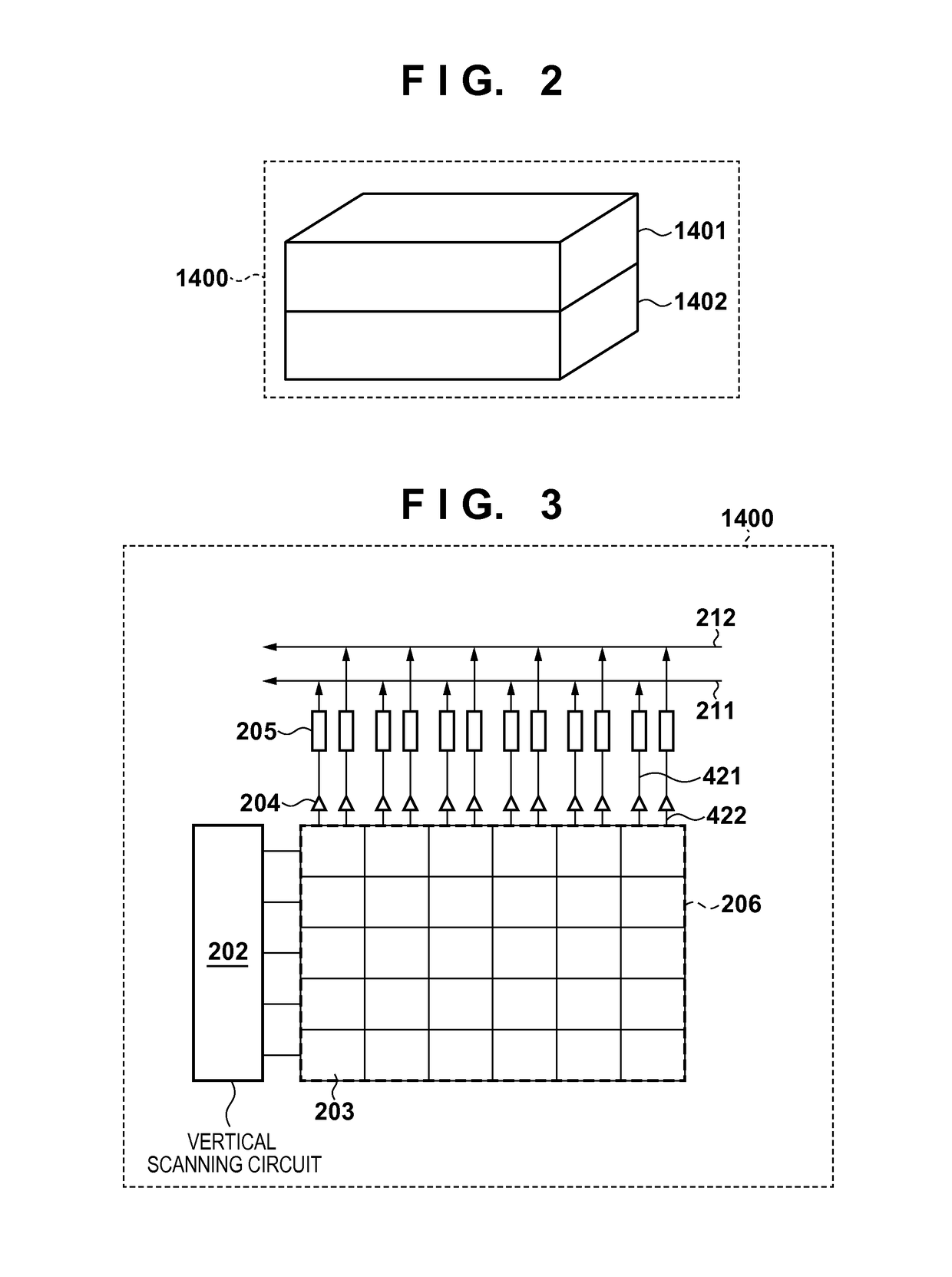
[0101]FIG. 15 is a block diagram showing a configuration of an image sensor according to the third embodiment. Regarding the pixels, the column amplifiers 204, the column circuits 205 and the like, the column amplifier and the c...
PUM
 Abstract
Description
Claims
Application Information
 - R&D
- Intellectual Property
- Life Sciences
- Materials
- Tech Scout
- Unparalleled Data Quality
- Higher Quality Content
- 60% Fewer Hallucinations
Browse by: Latest US Patents, China's latest patents, Technical Efficacy Thesaurus, Application Domain, Technology Topic, Popular Technical Reports.
© 2025 PatSnap. All rights reserved.Legal|Privacy policy|Modern Slavery Act Transparency Statement|Sitemap|About US| Contact US: help@patsnap.com


