
Corn milling process

a corn milling and process technology, applied in cocoa, solid separation, agriculture, etc., can solve the problems of process not separating all recoverable germs, undesirable degradation of germ streams, etc., and achieve the effect of not reducing the size of germs

Active Publication Date: 2012-02-14
CEREAL ENTERPRISES
View PDF9 Cites 11 Cited by
  • Summary
  • Abstract
  • Description
  • Claims
  • Application Information

AI Technical Summary

Benefits of technology

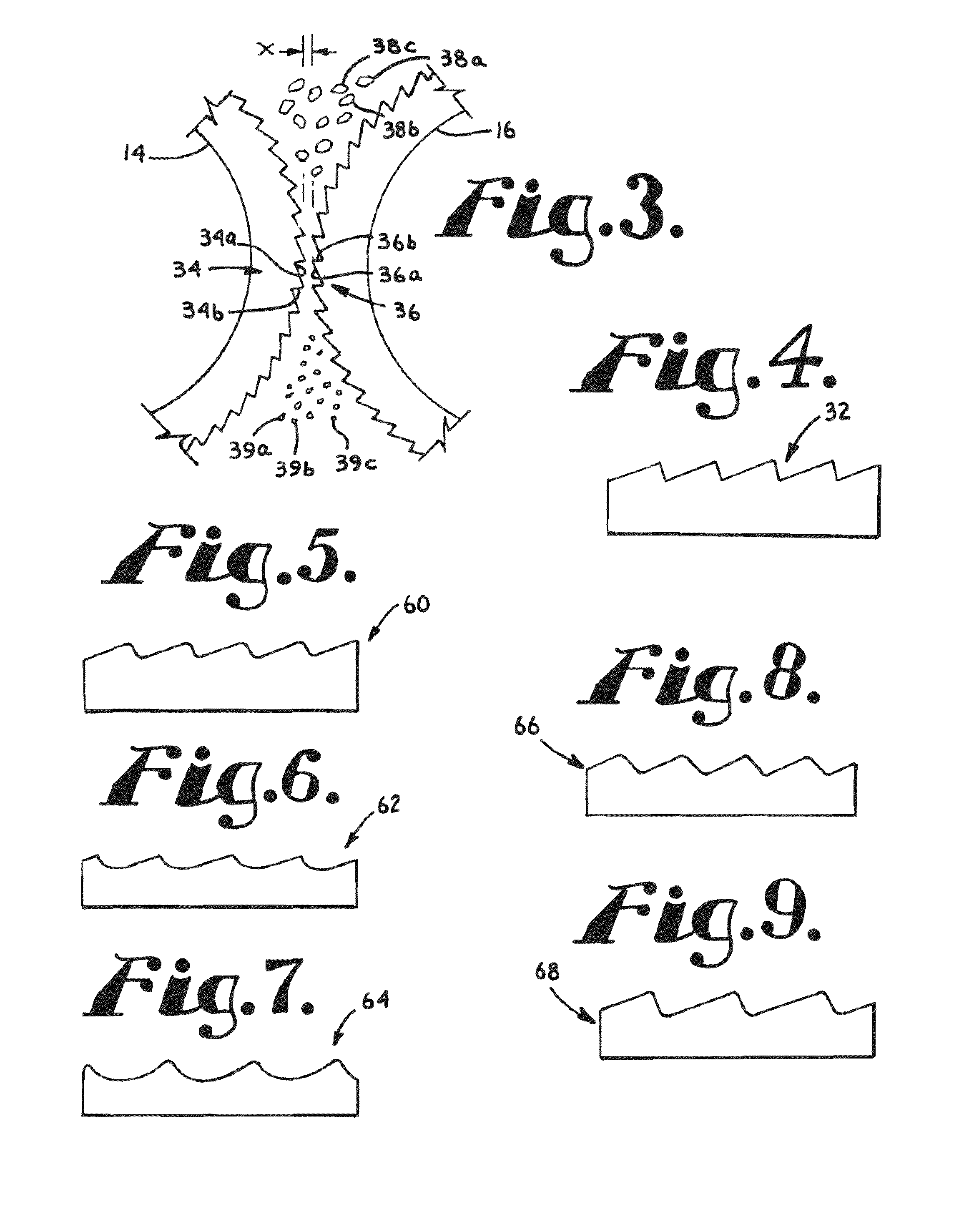
[0011]The corn milling process according to the present invention starts by fracturing corn kernels into relatively large particles at least some of which comprise both an endosperm and a germ portion of the kernels. Next, the fractured particles are passed between a pair of counter-rotating rollers, each of which presents fine corrugations of the type that normally characterizes the end of a differential corn milling process. The rollers rotate at different speeds thereby allowing the corrugations to grind the endosperm portion of the particles. The ratio of the roll speeds between the differential rollers is preferably between approximately 1.1-1.4:1, more preferably between approximately 1.2-1.35:1, and most preferably approximately 1.3:1. The rollers are spaced apart a distance to grind the endosperm portion of the particles while avoiding substantial penetration of the roller corrugations into the germ portion of the particles to achieve separation of the germ and endosperm without reducing the size of the germ.
[0012]The corn milling process of the present invention has achieved significant increases in yield over both of the previously known processes described above. When compared with the assignee's previous process having a roll speed differential of 1.6:1, the process of the present invention has increased oil yield after first break by approximately 6%, while at the same time producing an endosperm stream having a higher concentration of starch. Because the process of the present invention achieves better separation of the germ and endosperm after first break, the process recovers more oil, that oil is of higher quality due to undergoing a reduced number of grinding steps, and the endosperm stream is more pure.

Problems solved by technology

This gradual reduction process subjects corn kernels to multiple grinding and separating steps which can cause undesirable degradation of the germ stream.
Further, the process does not separate all of the recoverable germ, and the oil contained therein, from the endosperm stream.

Method used


Image

  • Corn milling process
  • Corn milling process
  • Corn milling process

Examples


Embodiment Construction

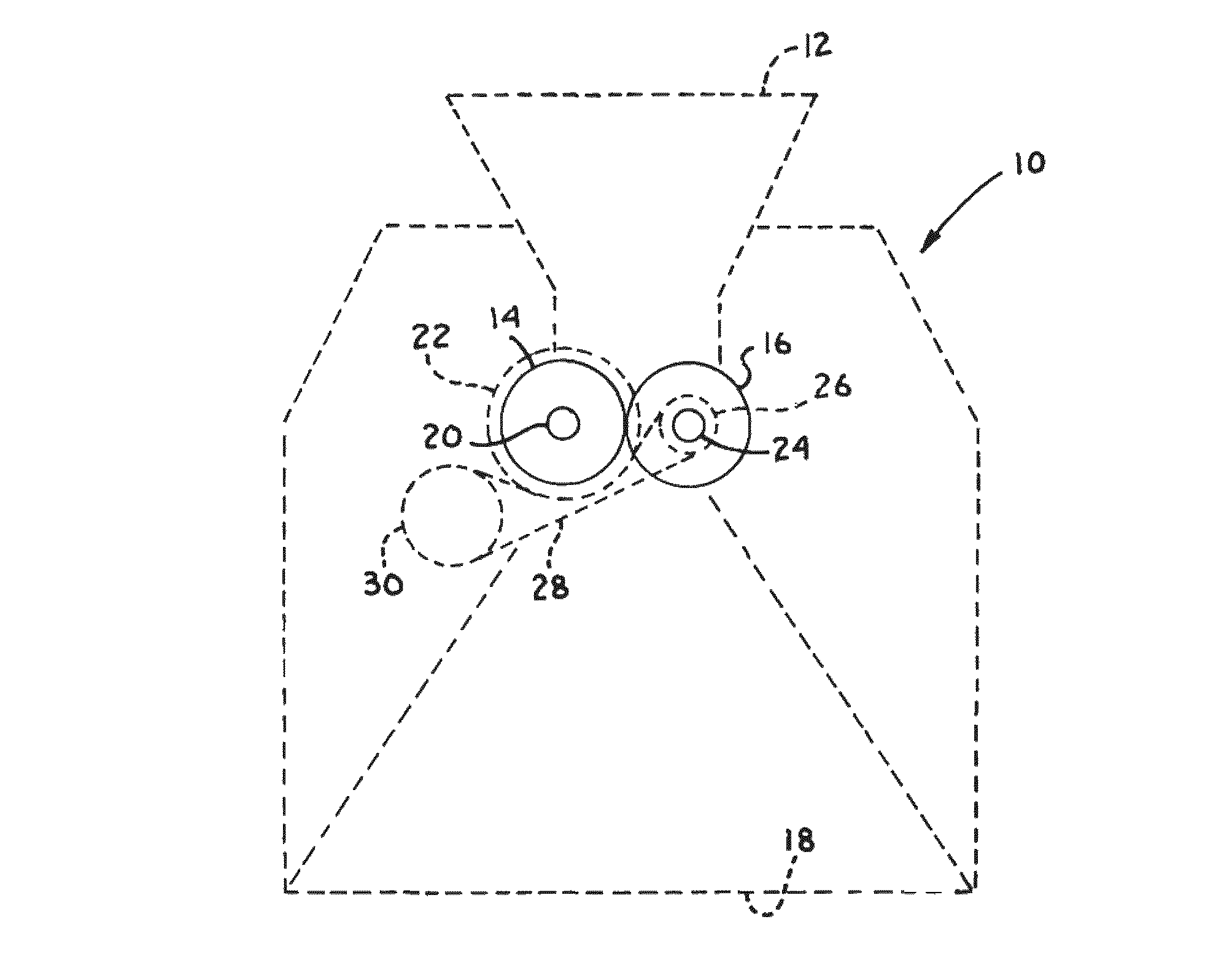
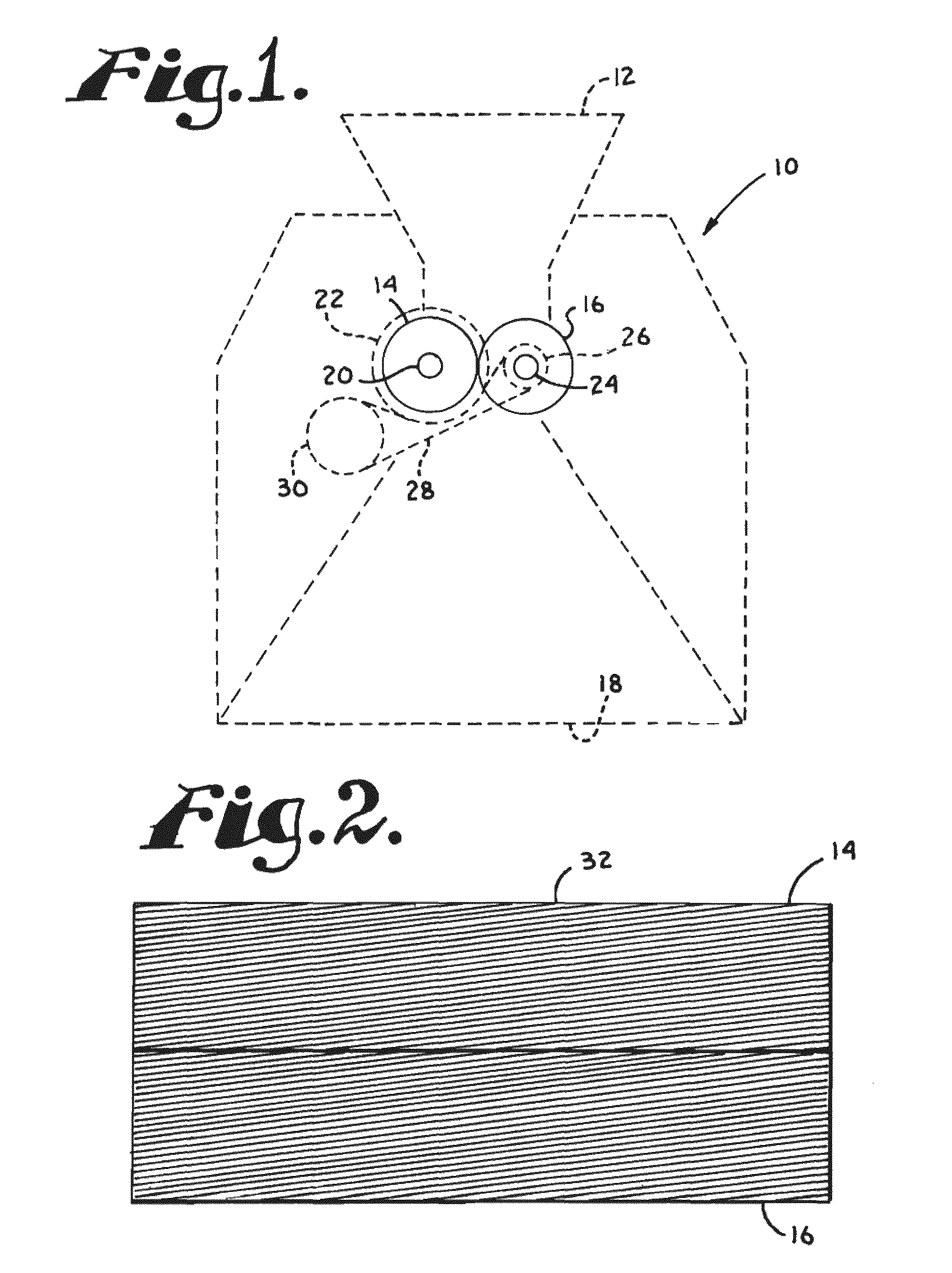
[0028]Referring to FIGS. 1-4, a differential roller mill for use with the corn milling process according to the present invention is shown generally as 10. As shown in FIG. 1, the roller mill has an input 12 which receives fractured corn kernels, a pair of counter-rotating rollers 14 and 16 positioned below the input 12 for separating the endosperm, germ, and bran portions of the fractured corn kernels, and an output 18 through which the separated particles pass. Roller 14 is mounted on a shaft 20 along with a pulley 22, and roller 16 is mounted on a shaft 24 along with a pulley 26. A drive belt 28 engages pulleys 22 and 24 and a drive pulley 30 which is coupled with a motor for rotating the pulleys. The belt 28 engages the pulleys 22 and 24 so that the pulleys rotate in opposite directions for effecting counter rotation of rollers 14 and 16. Additionally, pulley 22 is larger than pulley 24 so that roller 14 rotates at a slower rate than roller 16.

[0029]As shown in FIG. 2, each of t...


PUM


Abstract

A corn milling process comprising fracturing corn kernels into relatively large particles, and passing the fractured particles between a pair of counter-rotating rollers, each of which presents fine corrugations of the type that normally characterizes the end of a differential corn milling process. The ratio of the roll speeds between the differential rollers is between approximately 1.1-1.4:1. The rollers are spaced apart a distance to grind the endosperm portion of the corn kernel particles while avoiding substantial penetration of the roller corrugations into the germ portion of the particles thereby separating the germ and endosperm portions without reducing the size of the germ.

Description

CROSS-REFERENCE TO RELATED APPLICATIONS[0001]Not Applicable.STATEMENT REGARDING FEDERALLY SPONSORED RESEARCH OR DEVELOPMENT[0002]Not Applicable.BACKGROUND OF THE INVENTION[0003]1. Field of the Invention[0004]The present invention relates to grain milling generally, and more particularly, to an improved differential corn milling process.[0005]2. Description of Related Art[0006]In a conventional corn milling process, corn kernels are cleaned, tempered, and then sent to a degerminator, which attempts to remove the germ from each kernel without substantially grinding the germ. The corn particles exiting the degerminator are separated into “tail” and “thru” streams, the former being relatively rich in endosperm and the latter being relatively rich in bran and germ. Each stream is then preferably passed through aspirators for bran removal and gravity tables to achieve further sorting of each stream by particle density.[0007]Next, each stream is passed through a series of differential roll...

Claims


Application Information

Patent Timeline
Patent Type & Authority Patents(United States)
IPC IPC(8): B02C9/04
CPCB02C9/02
Inventor GIGUERE, R. JAMES
Owner CEREAL ENTERPRISES
Learn More