Crystal-oscillating device and manufacturing method therefor

a technology manufacturing method, which is applied in the direction of electrical apparatus, impedence network, etc., can solve the problems of inability to obtain stable q value and affect the q value of crystal oscillating device, so as to achieve accurate crystal oscillating device, stable q value, and stable q value.

Active Publication Date: 2019-12-17
MURATA MFG CO LTD
View PDF24 Cites 1 Cited by
  • Summary
  • Abstract
  • Description
  • Claims
  • Application Information

AI Technical Summary

Benefits of technology

[0009]An object of the present disclosure is to provide a crystal-oscillating device that can be reduced in size and has a favorable Q value, and a manufacturing method for the crystal-oscillating device.
[0020]In the crystal-oscillating device and the manufacturing method for the crystal-oscillating device, the crystal resonator and the second packaging material are formed from the same crystal substrate. Therefore, it is possible to accurately mount the crystal resonator on the size-reduced packaging material without reducing the size of the crystal resonator. Accordingly, a oscillation portion of the crystal resonator is ensured with a sufficient size, and it is possible to stably obtain a favorable Q value. In addition, in the crystal-oscillating device according to the present invention, since the crystal resonator and the first to third packaging materials are not directly connected to each other, stress or oscillation from the packaging materials is hard to propagate to the crystal resonator.
[0021]Therefore, according to the crystal-oscillating device and the manufacturing method for the crystal-oscillating device as disclosed herein, it is possible to provide a crystal-oscillating device that is allowed to be reduced in size and has a favorable Q value.

Problems solved by technology

In this case, it is not possible to ensure a sufficient oscillation portion, which, as a result, impairs the Q value of the crystal resonator in some cases.
In addition, in a configuration in which a crystal resonator is directly connected to a packaging material as in Patent Document 2, a stable Q value cannot be obtained in some cases due to oscillation or stress from the packaging material propagating to the crystal resonator.

Method used


Image

  • Crystal-oscillating device and manufacturing method therefor
  • Crystal-oscillating device and manufacturing method therefor
  • Crystal-oscillating device and manufacturing method therefor

Examples


Embodiment Construction

[0030]Hereinafter, specific embodiments of the present invention will be described with reference to the drawings to clarify the present invention and disclosure herein.

[0031](Crystal Vibration Device)

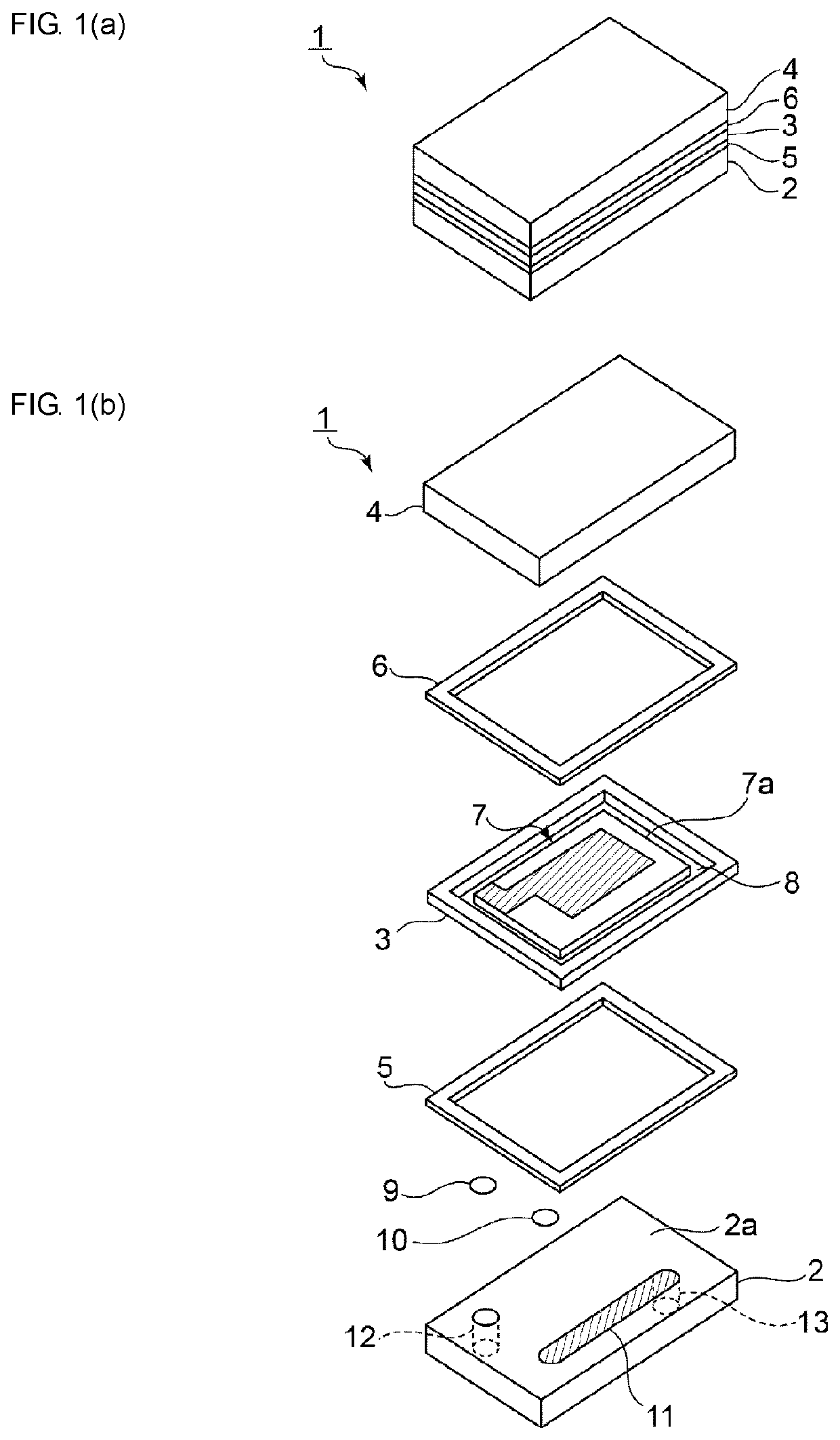
[0032]FIG. 1(a) is a perspective view of a crystal-oscillating device according to an embodiment of the present invention, and FIG. 1(b) is an exploded perspective view of the crystal-oscillating device.

[0033]The crystal-oscillating device 1 includes a first packaging material 2 having a crystal resonator mounting surface 2a. In the present embodiment, the first packaging material 2 has a rectangular plate shape. Preferably, the first packaging material 2 is formed from an AT-cut crystal substrate. However, the first packaging material 2 may be formed from an insulating ceramic material such as alumina or an appropriate insulating material such as a synthetic resin, and the material of the first packaging material 2 is not particularly limited.

[0034]A crystal resonator 7 is mounted on ...


PUM


Abstract

A crystal-oscillating device is disclosed with a reduction in size and a favorable Q value. The crystal-oscillating device includes a first packaging material; a crystal resonator mounted on the first packaging material; joining members that join the first packaging material to the crystal resonator; a first sealing frame for joining the second and third packaging materials, the first packaging material, and the second packaging material; and a second sealing frame for joining the second packaging material and the third packaging material to each other. Preferable, the second packaging material is formed in a frame shape to surround an outer peripheral edge of the crystal resonator, and the second packaging material and a crystal substrate of the crystal resonator are formed from the same crystal substrate.

Description

CROSS REFERENCE TO RELATED APPLICATIONS[0001]The present application is a continuation of PCT / JP2015 / 052118 filed Jan. 27, 2015, which claims priority to Japanese Patent Application No. 2014-090080, filed Apr. 24, 2014, the entire contents of each of which are incorporated herein by reference.TECHNICAL FIELD[0002]The present disclosure relates to a crystal-oscillating device in which a crystal resonator is sealed by a packaging material.BACKGROUND[0003]Crystal-oscillating devices have been widely used in portable electronic apparatuses. For example, Patent Document 1 identified below discloses a crystal-oscillating device in which a crystal oscillation plate is sealed by a packaging material. In Patent Document 1, the crystal oscillation plate and the packaging material are connected and fixed to each other by an inner electrode.[0004]In addition, Patent Document 2 identified below discloses a crystal-oscillating device that includes a crystal resonator and a packaging material havi...

Claims


Application Information

Patent Timeline
Patent Type & Authority Patents(United States)
IPC IPC(8): H03H9/10H03H9/17
CPCH03H9/17H03H9/10H03H9/02H03H9/1021H03H9/171
Inventor IKEDA, ISAOFURUI, JINYA
Owner MURATA MFG CO LTD
Why Eureka
Try Eureka