Image capturing apparatus and method for controlling the image capturing apparatus

Active Publication Date: 2015-06-11
CANON KK
View PDF8 Cites 4 Cited by
  • Summary
  • Abstract
  • Description
  • Claims
  • Application Information

AI Technical Summary

Benefits of technology

[0007]The present invention has been made in consideration of the above situation, and provi

Problems solved by technology

However, the provision of a plurality of CCDs in a single pixel in a solid-state image capturing apparatus including an increasing number of p

Method used


Image

  • Image capturing apparatus and method for controlling the image capturing apparatus
  • Image capturing apparatus and method for controlling the image capturing apparatus
  • Image capturing apparatus and method for controlling the image capturing apparatus

Examples


first embodiment

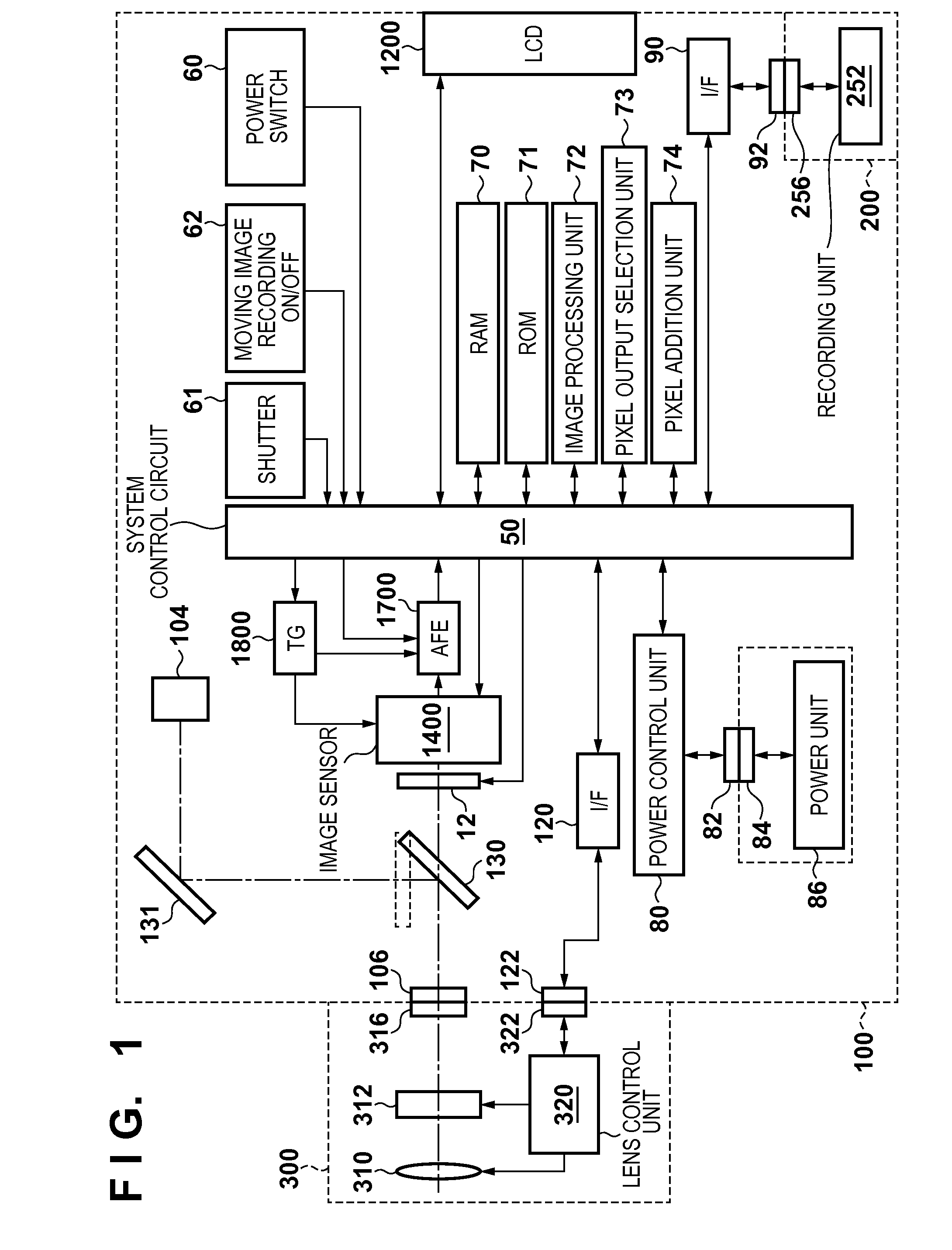
[0043]FIG. 1 is a block diagram showing a configuration of an image capturing apparatus according to a first embodiment of the present invention. The image capturing apparatus mainly includes an image processing apparatus 100, a recording medium 200 such as a memory card or a hard disk, and a lens unit 300.

[0044]The lens unit 300 includes a taking lens 310, an aperture 312, a lens mount 316, a lens control unit 320, and a connector 322. The lens mount 316 mechanically connects the lens unit 300 to a lens mount 106 of the image processing apparatus 100. The connector 322 is electrically connected to the image processing apparatus 100 via a connector 122 on the image processing apparatus 100 side. The lens control unit 320 receives a signal from the image processing apparatus 100 via the connectors 322 and the 122, and performs focus adjustment by changing the position of the taking lens 310 on the optical axis in accordance with the received signal. The lens control unit 320 receives...

second embodiment

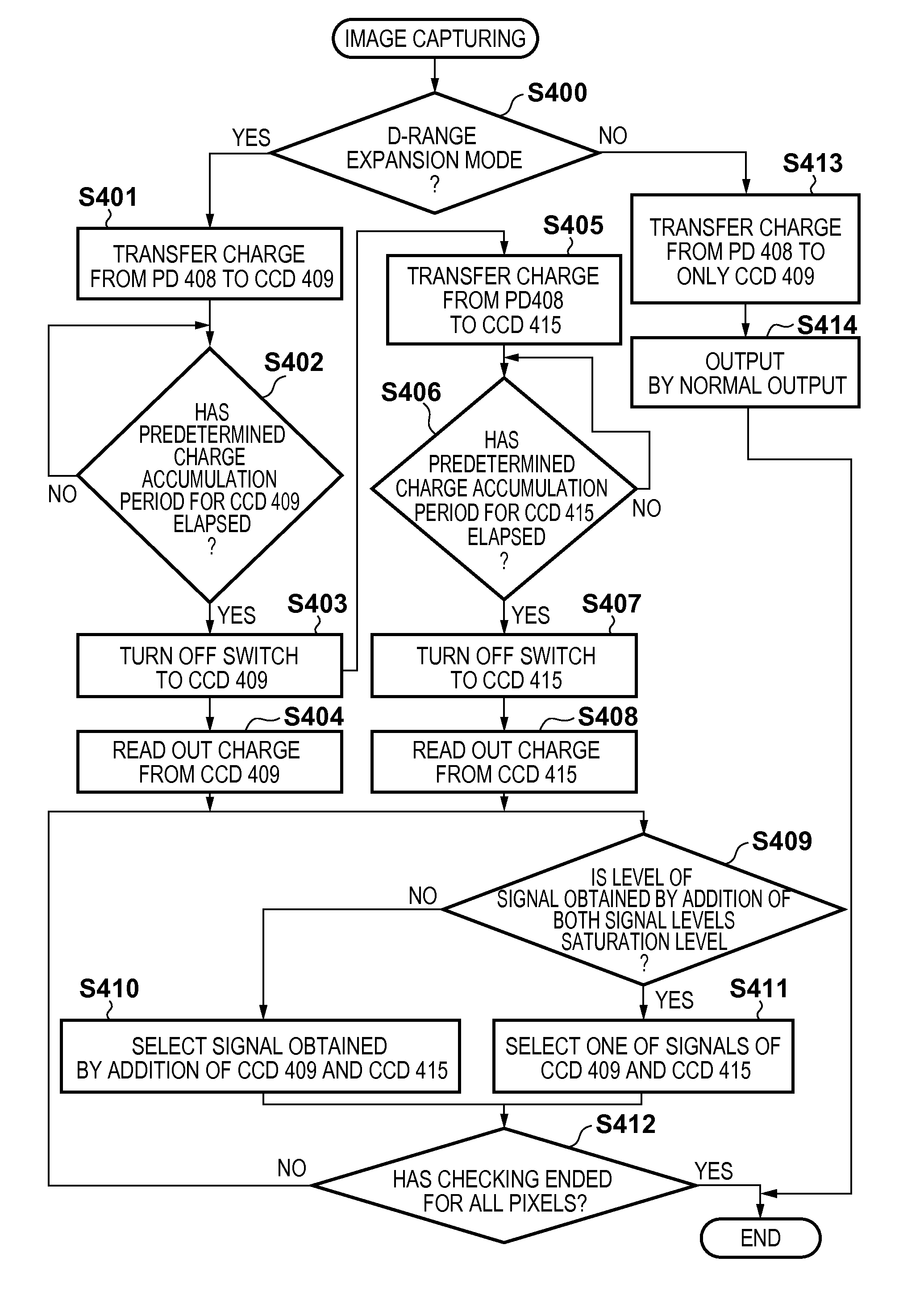
[0086]Next, a second embodiment of the present invention will be described. Note that the configurations of the image capturing apparatus and the image sensor according to the second embodiment are the same as those described with reference to FIGS. 1 to 4B in the first embodiment described above, and therefore, the description thereof shall be omitted here. In the second embodiment, each of the CCDs 409 and 415 is driven at the same timing such that the charge accumulation period is the same, and whether to add or independently output the two outputs in a later stage is selected.

[0087]With reference to FIGS. 11 and 12, a description will be given of charge transfer by a readout scheme according to the second embodiment. FIG. 11 shows a timing chart of control signals according to the second embodiment. FIG. 12 shows a potential transition diagram according to the second embodiment. Note that the control of the control signals φ400 to φ407 shown in FIG. 11 is performed by the CPU 50...

third embodiment

[0100]Next, a third embodiment of the present invention will be described. Note that the configurations of the image capturing apparatus and the image sensor according to the third embodiment are different in the configuration of the image sensor 1400 from those described with reference to FIGS. 1 to 4B in the first embodiment described above. The rest of the configurations are the same, and therefore, the description thereof shall be omitted here. Additionally, in the third embodiment, as with the second embodiment, each of the CCDs 409 and 415 is driven at the same timing as shown in FIG. 11 such that the charge accumulation period is the same. Different gains are applied to the column amplifiers when the charge is readout from each of the CCDs 409 and 415.

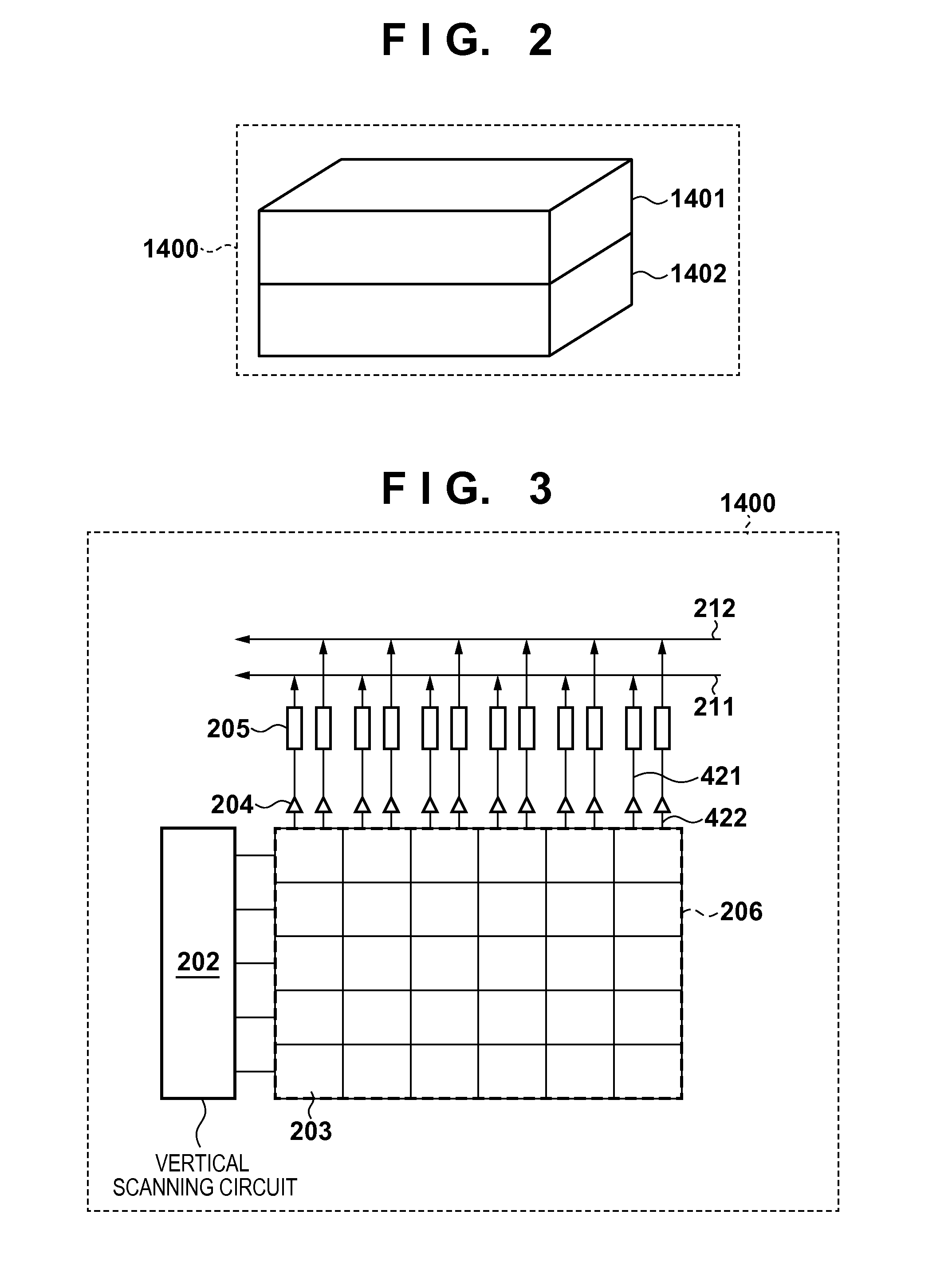
[0101]FIG. 15 is a block diagram showing a configuration of an image sensor according to the third embodiment. Regarding the pixels, the column amplifiers 204, the column circuits 205 and the like, the column amplifier and the c...


PUM


Abstract

An image capturing apparatus comprises an image sensor and a generation unit configured to generate a signal of each of the pixels from the signals respectively read out from the plurality of charge accumulation units. The image sensor includes a plurality of pixels, each of the pixels including: a photoelectric conversion unit; a plurality of charge accumulation units for accumulating a charge generated in the photoelectric conversion unit; a control unit configured to control accumulation of charge in each of the plurality of charge accumulation units; and a readout unit configured to read out a signal corresponding to the charge from each of the plurality of charge accumulation units. The photoelectric conversion unit is formed in a first chip, and the plurality of charge accumulation units, the control unit, and the readout unit are formed in a second chip.

Description

BACKGROUND OF THE INVENTION[0001]1. Field of the Invention[0002]The present invention relates to an image capturing apparatus that uses an image sensor typified by a CMOS image sensor, and a method for controlling the image capturing apparatus.[0003]2. Description of the Related Art[0004]An increasing number of recent electronic cameras and video cameras include a CMOS image sensing device mounted thereon. A commonly used CMOS image sensing device employs a scheme in which signal charges generated and accumulated in photoelectric conversion units of pixels arranged in a two-dimensional matrix are sequentially read out on a row-by-row basis. In recent years, a simultaneous image capturing function (global shutter function) of accumulating signal charges at the same timing has been proposed, and the applications of a CMOS image sensing element having the global shutter function are also increasing.[0005]According to Japanese Patent Laid-Open No. 2011-217315, a plurality of CCDs servin...

Claims


Application Information

Patent Timeline
IPC IPC(8): H04N5/374H04N5/378
CPCH04N5/378H04N5/3741H04N25/583H04N25/59H04N25/771H04N25/75H04N5/30H04N25/76H04N23/681H04N23/683H04N25/766
Inventor NISHIZAWA, HIDETA
Owner CANON KK
Why Eureka
Try Eureka