Stator assembly for motor having hall sensor part fixed to end of tooth of stator

a stator and motor technology, applied in the direction of magnet circuit shape/form/construction, solid insulation, windings, etc., can solve the problems of increasing the amount of resin consumption for ejection molding, and raising the material cost, so as to reduce the amount of resin consumption without reducing the size of the slo

Active Publication Date: 2015-11-24
NEW MOTECH
View PDF20 Cites 1 Cited by
  • Summary
  • Abstract
  • Description
  • Claims
  • Application Information

AI Technical Summary

Benefits of technology

[0022]The present invention provides a stator assembly and a method for manufacturing the same that enables insulation of the teeth without reducing the size of slots, remarkably reduces the amount of resin consumption for resin molding, and makes it possible to arbitrarily determine the position of the hole sensor portion.

Problems solved by technology

This makes a difference in physical characteristics, such as a change in the magnetic flux through a constant number of windings, and adversely leads to an increase in the amount of resin consumption for ejection molding.
When needed to selectively form the coupling bushing 151 and a hole sensor coupling portion 155 on the insulator 150 as shown in FIG. 2, the process requires an increase in the amount of resin consumption for ejection molding increases as well as more complicated molds, thus raising the material cost.

Method used


Image

  • Stator assembly for motor having hall sensor part fixed to end of tooth of stator
  • Stator assembly for motor having hall sensor part fixed to end of tooth of stator
  • Stator assembly for motor having hall sensor part fixed to end of tooth of stator

Examples


Embodiment Construction

[0032]Hereinafter, an explanation on the preferred embodiments of the present invention will be given in detail with reference to the attached drawings.

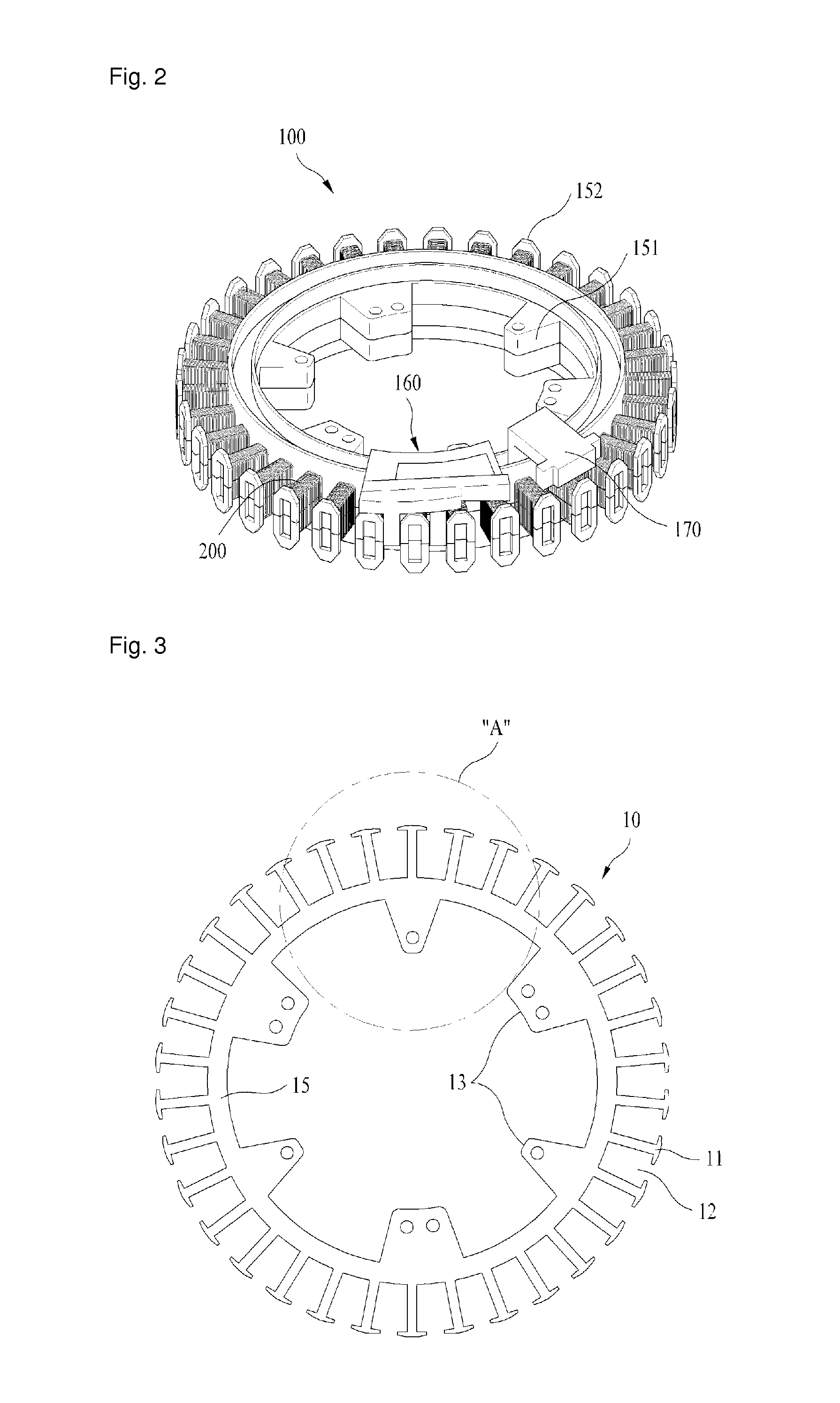
[0033]FIG. 3 is a plan view showing a stator core used for a stator assembly according to the present invention.

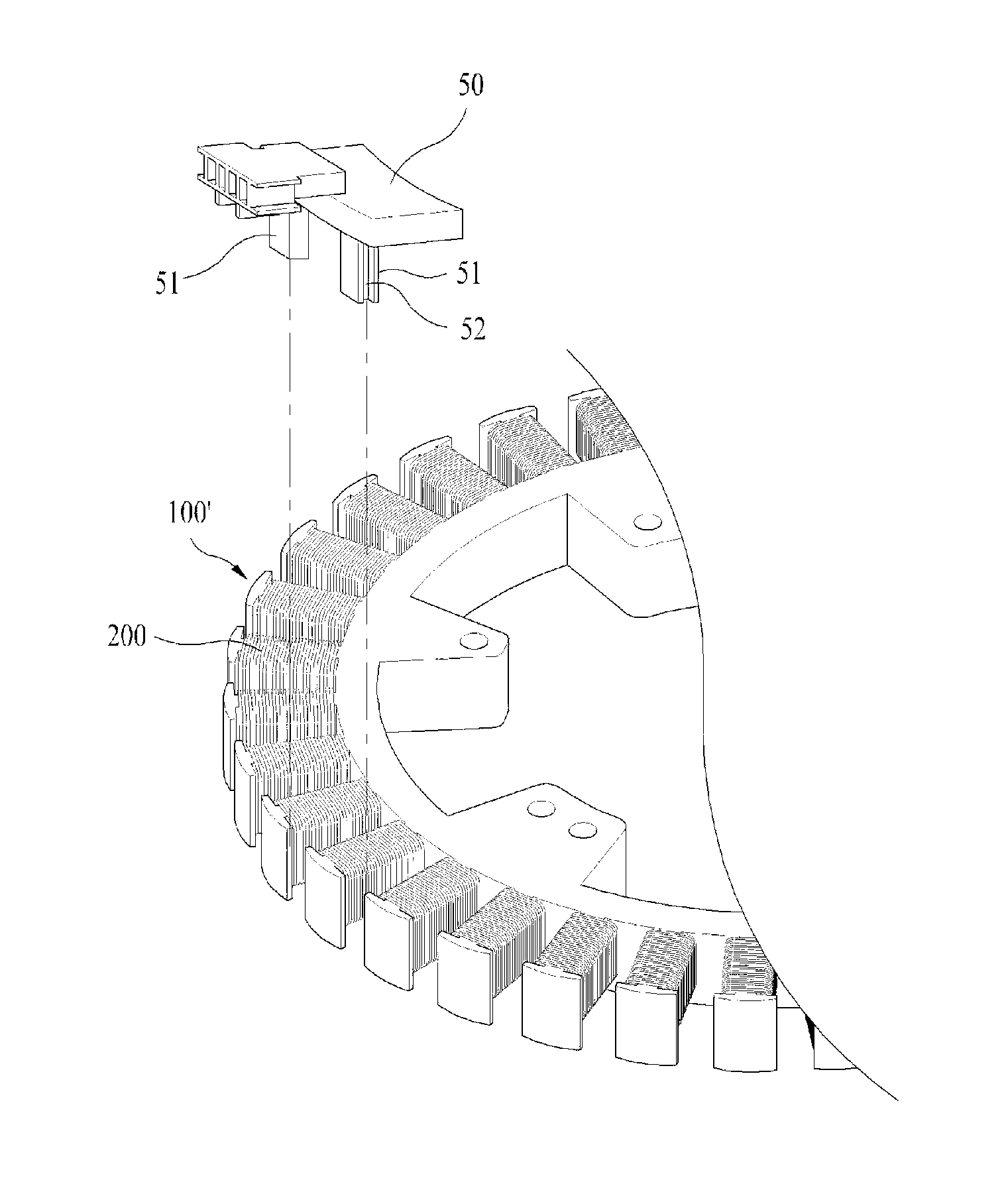
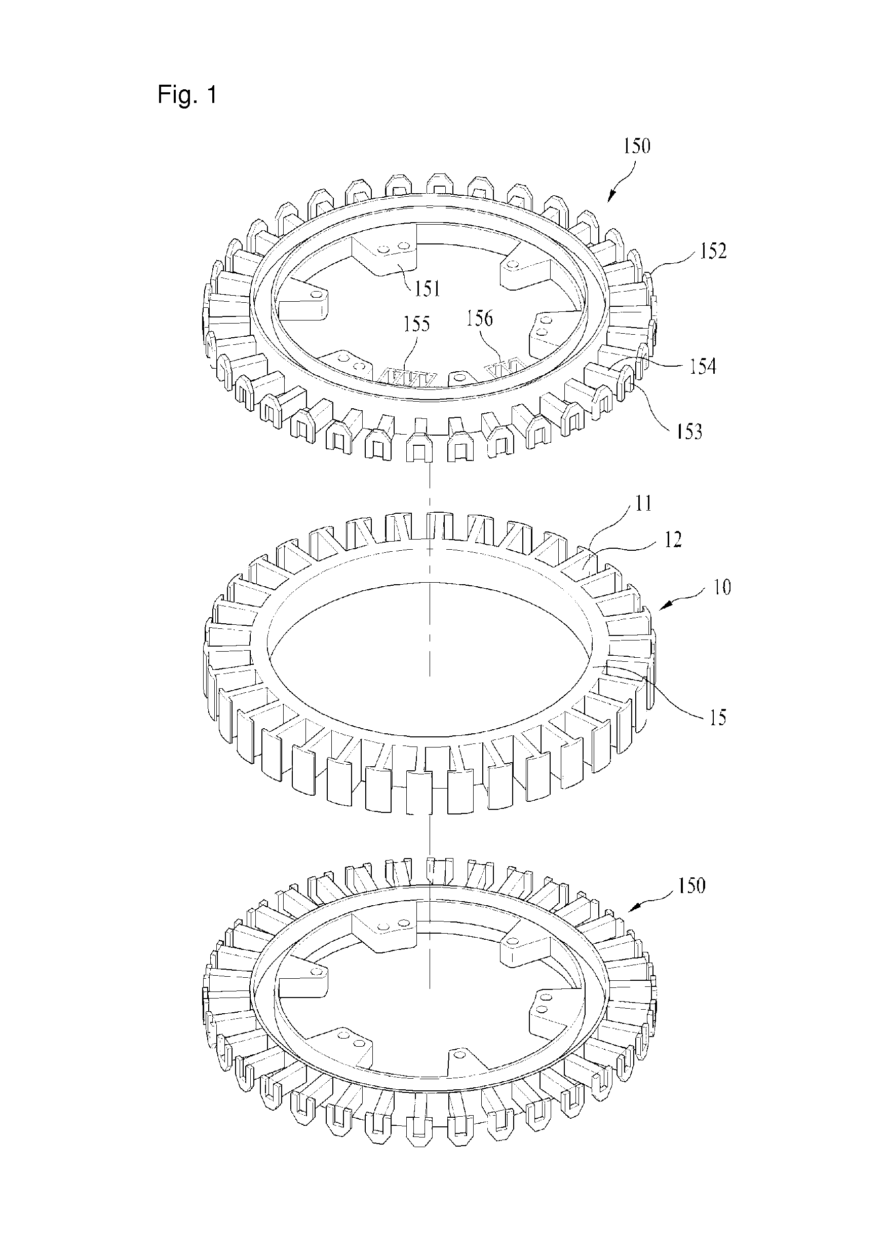
[0034]As shown in FIG. 3, which presents an overhead plan view, the stator core 10 of a stator assembly according to the present invention is prepared from a lamination of a film type steel sheet. The stator core 10 includes a circular base 15, a plurality of teeth 11 radially formed on an outer circumference of the base 15, and a slot 12 providing a space between the adjacent teeth 11. On an inner circumference of the base 15 are formed six coupling bushings 13 provided for fixedly coupling a stator. The number of the coupling bushings 13 is, of course, not limited to six. The present invention is not specifically limited to an outer rotor type stator assembly as illustrated herein, and may also be applied to an inner roto...


PUM

PropertyMeasurementUnit
circumferenceaaaaaaaaaa
magnetic fluxaaaaaaaaaa
thicknessaaaaaaaaaa

Abstract

The present invention relates to a stator assembly that includes: a stator core having a circular base, a plurality of teeth radially formed along an outer circumference of the base, and at least one coupling bushing formed along an inner circumference of the base; an insulation coating layer formed on an surface of the stator core; and a pair of base insulators coupled to top and bottom portions of the base, respectively.

Description

CROSS REFERENCE TO PRIOR APPLICATIONS[0001]This application is a National Stage Patent Application of PCT International Patent Application No. PCT / KR2011 / 001593 (filed on Mar. 8, 2011) under 35 U.S.C. §371, which claims priority to Korean Patent Application No. 10-2010-0041817 (filed on May 4, 2010), which are all hereby incorporated by reference in their entirety.TECHNICAL FIELD[0002]The present invention relates to a motor. More particularly, the present invention relates to a stator assembly having a novel structure applied to motors.BACKGROUND ART[0003]Generally, a motor of which the rotor is positioned on an outer side of a stator is called “outer rotor type motor”, while a motor with its rotor positioned on an inner side of a stator is called “inner rotor type motor”. The present invention relates to a stator assembly for outer rotor type DD (Direct Driving) motor used for washing machines, or for inner rotor type motor mainly used for air conditioners.[0004]FIG. 1 is an explo...

Claims


Application Information

Patent Timeline
Patent Type & Authority Patents(United States)
IPC IPC(8): H02K3/32H02K15/10H02K29/08H02K3/52H02K1/12H02K3/38H02K1/18H02K3/34H02K11/00H02K1/14
CPCH02K1/12H02K3/325H02K3/38H02K3/522H02K15/10H02K29/08H02K1/146H02K1/187H02K2203/12Y10T29/49009
Inventor JANG, JEONG CHEOLLEE, JI MIN
Owner NEW MOTECH
Why Eureka
Try Eureka