Method and apparatus for signaling control information of uplink packet data service in mobile communication system

a mobile communication system and packet data technology, applied in the field of mobile communication system for transmitting packet data, can solve the problems of poor uplink channel status, interference of uplink signals with each other, and degrade the reception performance of uplink signals

Active Publication Date: 2009-06-23
SAMSUNG ELECTRONICS CO LTD
View PDF18 Cites 35 Cited by
  • Summary
  • Abstract
  • Description
  • Claims
  • Application Information

AI Technical Summary

Problems solved by technology

In an uplink, since orthogonality is not maintained between signals transmitted from a plurality of UEs, the uplink signals interfere with each other.
In this case in which a scheduling for the E-DCH packet traffic is not performed, if a plurality of UEs may simultaneously transmit packet data at high data rates, the total ROT may exceed a target ROT, which degrades the reception performance of the uplink signals.
In contrast, if the difference between the transmission power and the reception power is large, the uplink channel status is bad.

Method used


Image

  • Method and apparatus for signaling control information of uplink packet data service in mobile communication system
  • Method and apparatus for signaling control information of uplink packet data service in mobile communication system
  • Method and apparatus for signaling control information of uplink packet data service in mobile communication system

Examples


exemplary embodiment 1

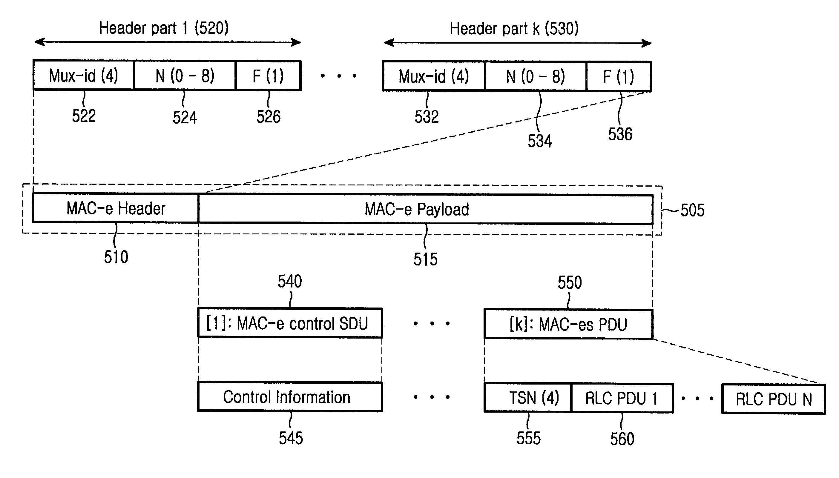
[0060]FIG. 5 is a block diagram illustrating the structure of a MAC-e PDU according to a first exemplary implementation of an embodiment of the present invention. A MAC-e PDU 505 is a data provided through a transmission channel to a physical layer, and includes a MAC-e header 510 and a MAC-e payload 515.

[0061]The MAC-e payload 515 of the MAC-e PDU 505 can contain at least one MAC-es PDU 550, and the MAC-e header 510 includes multiplexing information relating to the MAC-es PDU 550. The MAC-e payload 515 can contain RLC PDUs created from a plurality of RLC entities, in which RLC PDUs 560 created from the same RLC entity are contained to be located close to each other in the MAC-e PDU 505. That is, The RLC PDUs 560 and the TSN 555 created from the same RLC entity are contained in one MAC-es PDU 550. The TSN 555 is information used for the reordering of the MAC-es PDU 550. In addition, the MAC-e payload 515 can contain a MAC-e control service data unit (MAC-e control SDU) 540 containin...

exemplary embodiment 2

[0081]According to the first exemplary implementation of an embodiment of the present invention, a multiplexing identifier included in a MAC-e header of a MAC-e PDU is used to identify a logical channel, a reordering queue, and an RLC PDU size. Different from the first embodiment, the second exemplary implementation of an embodiment of the present invention uses a data description indicator (DDI) in order to identify a MAC-d flow instead of the reordering queue. The combination of a logical channel, a reordering queue, and an RLC PDU size is identical to the combination of a logical channel, a MAC-d flow, and an RLC PDU size, in view that both include information about the size of RLC PDUs contained in a MAC-es PDU and information about an upper layer to which the RLC PDUs will be transmitted. The second exemplary implementation of an embodiment of the present invention uses a DDI, which is a logical identifier for identifying a logical channel, a MAC-d flow, and an RLC PDU size, in...

exemplary embodiment 3

[0103]According to the first exemplary embodiment, a special DDI value representing a MAC-e control SDU is used for a DDI field, and an N field relating to the DDI field is used to represent a kind of control information inserted into the MAC-e control SDU.

[0104]FIG. 12 is a block diagram illustrating the structure of a MAC-e PDU according to the third exemplary implementation of an embodiment of the present invention. A MAC-e PDU 1240 includes a MAC-e header 1245 and a MAC-e payload 1250, and the MAC-e header 1245 includes k number of header parts 1205, 1210, and 1215. The header parts 1205 to 1215 one-to-one correspond to components included in the MAC-e payload 1250. The MAC-e header part #11205 corresponding to a first MAC-es PDU 1255 is configured with a DDI field 1220 (which represents a logical channel, a MAC-d flow, and an RLC PDU size) and an N field 1225 for representing the number of RLC PDUs. The MAC-e header part #21210 is configured with a DDI field an N field for the ...


PUM


Abstract

A method and apparatus for transmitting control information relating to an uplink packet data service from a user equipment (UE) to a Node B in a mobile communication system are provided. MAC-es protocol data units (PDUS) including data of an upper layer and a control service data unit (SDU) including control information of a MAC layer are multiplexed and contained in a MAC-e protocol data unit (PDU) transmitted in an uplink from the UE during one transmission period. In a header of the MAC-e PDU, a header part corresponding the control SDU contains a data description indicator (DDI) field set as a specific value representing that the control information is transmitted, and a header part corresponding to the MAC-es PDU contains a DDI field which represents a MAC-e flow and a logical channel relating to uplink packet data included in the second PDU, and a data size. Node B detects the control information from the control SDU based on the DDI field set as the specific value. Since the header part representing the control information has a structure similar to the header part representing the MAC-es PDU, the structure of the header is simplified, and the header size of the packet is minimized.

Description

PRIORITY[0001]This application claims the benefit under 35 U.S.C. 119(a) of Korean Patent Applications Serial Nos. 2004-91093 and 2004-109938, filed in the Korean Intellectual Property Office on Nov. 9, 2004 and Dec. 21, 2004, respectively, the entire contents of which are hereby incorporated by reference.BACKGROUND OF THE INVENTION[0002]1. Field of the Invention[0003]The present invention relates to a mobile communication system for transmitting packet data in uplink. More particularly, the present invention relates to a method and apparatus for efficiently signaling control information which is used to control an uplink packet data service.[0004]2. Description of the Related Art[0005]A European-type 3rd generation mobile communication system, which is based on Global System for Mobile communication (GSM) and General Packet Radio Services (GPRS) and uses an asynchronous wideband code division multiple access (WCDMA), utilizes an enhanced uplink dedicated channel (E-DCH or EUDCH). T...

Claims


Application Information

Patent Timeline
Patent Type & Authority Patents(United States)
IPC IPC(8): H04J3/24H04W28/00H04W28/06H04W72/04
CPCH04L29/06H04W28/06H04L1/1812H04L1/1829H04L1/1867H04L69/22H04L69/324H04L9/40
Inventor KIM, SOENG-HUNVAN LIESHOUT, GERT JAN
Owner SAMSUNG ELECTRONICS CO LTD
Why Eureka
Try Eureka