Electrical drive arrangement for a fuel injection system

a technology of electric drive and fuel injection system, which is applied in the direction of electric control, charge feed system, fuel injection apparatus, etc., can solve the problems of noise affecting the level and the electric drive arrangement does not operate under ideal conditions, so as to improve the load response of the voltage regulation device and increase the voltage input

Active Publication Date: 2009-06-30
DELPHI TECH IP LTD
View PDF3 Cites 1 Cited by
  • Summary
  • Abstract
  • Description
  • Claims
  • Application Information

AI Technical Summary

Benefits of technology

[0016]In another embodiment, a current sense element is connected between the capacitor element and the electrical ground connection, and a feedback path is connected therebetween to provide a injector voltage signal to the gate terminal of the filter device. This configuration provides the benefit that the voltage at the gate terminal of the field effect transistor is modified as a function of the load on the injector driver stage which adjusts the conductivity of the transistor thereby improving the load response of the voltage regulation device.

Problems solved by technology

A known problem is that such electrical drive arrangements do not operate under ideal conditions and are typically supplied with electrical power that is subject to spurious electrical oscillations, hereinafter referred to as ‘noise’.
However, some sources of noise are not predictable and such noise affects detrimentally the level of control that the ECU 10 has over the operational timing of the injectors 8.

Method used


Image

  • Electrical drive arrangement for a fuel injection system
  • Electrical drive arrangement for a fuel injection system
  • Electrical drive arrangement for a fuel injection system

Examples


Embodiment Construction

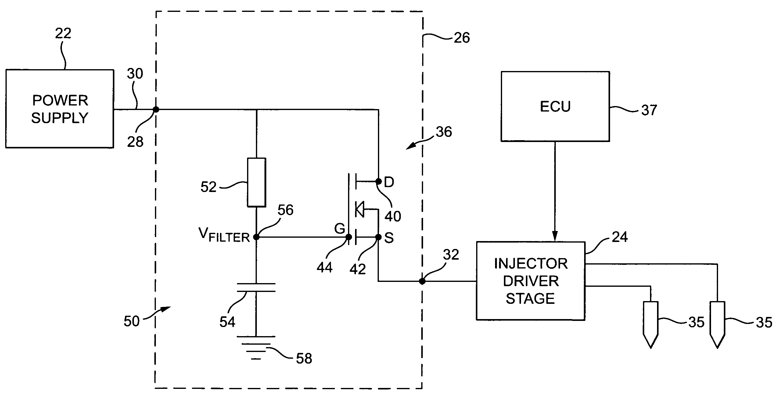
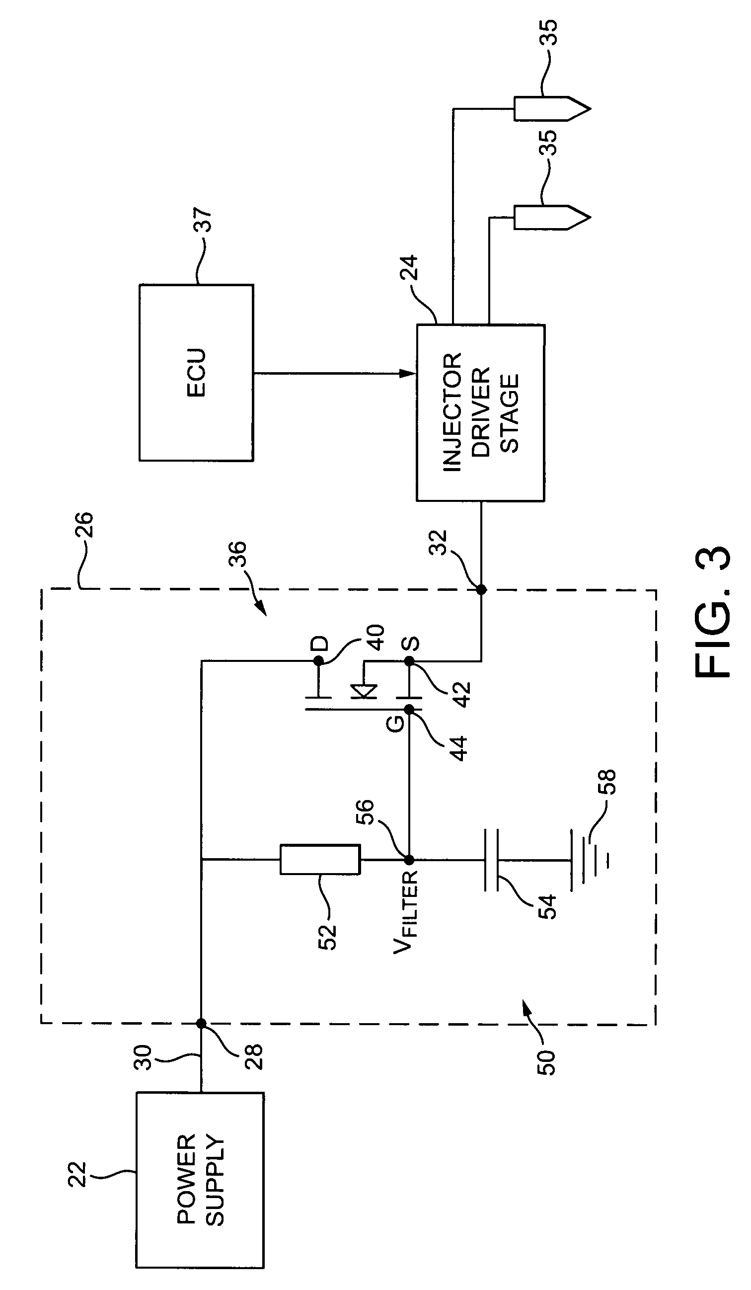
[0028]FIG. 2 shows an electrical drive arrangement 20 of a fuel injection system in which a power supply 22 is connected to an injector driver stage 24 via a voltage regulation device 26. The power supply 22 is connected to an input terminal 28 of the voltage regulation device 26 via a first voltage supply line 30 and an output terminal 32 of the voltage regulation device 26 is connected to the injector driver stage 24 via a second voltage supply line 34. Although not shown in FIG. 2, the power supply 22 is the battery of the vehicle in which the electrical drive arrangement 20 is installed. Typically, the power supply 22 supplies a nominal voltage of 12 or 24 Volts DC to the voltage regulation device 26 and, thus, to the injector driver stage 24.

[0029]Due to local electrical and electromagnetic influences, for example electrical components such as lighting and audio systems, emitters of electromagnetic interference such as vehicular-based telecommunication systems and the like, the...


PUM


Abstract

An electrical drive arrangement of a fuel injection system comprising a power supply operatively connected to an injector driver stage which, in turn, is operatively connected to at least one fuel injector. The electrical drive arrangement includes a voltage regulation device operatively connected between the power supply and the injector driver stage, wherein the voltage regulation device is arranged to regulate the voltage supply from the power supply to the injector driver stage.

Description

TECHNICAL FIELD [0001]The present invention relates to an automotive fuel injection system and, more particularly, to an electrical drive arrangement for use in such a fuel injection system.BACKGROUND ART[0002]Modern automotive vehicle engines are generally equipped with fuel injectors for injecting fuel (e.g. gasoline or diesel fuel) into the individual cylinders of the engine. The fuel injectors are coupled to a source of high pressure fuel that is delivered to the injectors by way of a fuel delivery system. The fuel injectors typically employ a valve needle that is actuated to disengage and re-engage an associated valve seat so as to control the amount of high pressure fuel that is metered from the fuel delivery system and injected into a corresponding engine cylinder. It is known to use solenoid operated injectors in which an electrically driven solenoid is operably connected to the valve needle. Energising the solenoid causes the valve needle to disengage from its seat, thus pe...

Claims


Application Information

Patent Timeline
Patent Type & Authority Patents(United States)
IPC IPC(8): F02M51/00
CPCF02D41/2096F02D2041/2051
Inventor ENGEL, JOSEPH A.NASCIMENTO, GERMANO D.CHIREZ, LAURENCEHERBIN, FRANCOISMARX, EDWIN H.HAU, MARVIN G.BLAGRAVE, JAMES J.
Owner DELPHI TECH IP LTD
Why Eureka
Try Eureka