
Control circuit capable of increasing power factor and revising load response

A technology for power factor correction and power improvement, which is applied to output power conversion devices, high-efficiency power electronic conversion, and conversion of AC power input to DC power output. The problem of slow ring response is solved, and the circuit structure is simple and reliable, the system cost is reduced, and the effect is easy to implement.

Active Publication Date: 2012-05-23
上海硅虹微电子科技有限公司
View PDF0 Cites 0 Cited by
  • Summary
  • Abstract
  • Description
  • Claims
  • Application Information

AI Technical Summary

Problems solved by technology

In order to reduce the total harmonic distortion and improve the power factor, the voltage loop uses a proportional integral link, so the loop bandwidth of the voltage loop is designed to be very narrow
And in order to reduce the magnitude of the ripple, the general circuit needs a large output capacitor
This causes the output voltage to change very slowly due to load changes
The response of the voltage loop designed in this way will be very slow, which cannot meet many applications.

Method used


Image

  • Control circuit capable of increasing power factor and revising load response
  • Control circuit capable of increasing power factor and revising load response
  • Control circuit capable of increasing power factor and revising load response

Examples


Embodiment Construction

[0015] The present invention will be further described below in conjunction with specific drawings and embodiments.

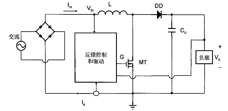
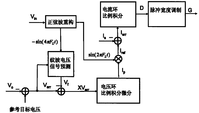
[0016] Such as figure 2 with 3 Shown: Taking the Boost structure power factor correction circuit as an example, the present invention includes a full-wave rectifier circuit, a Boost structure power factor correction circuit and a feedback control and drive module.

[0017] The full-wave rectifier circuit rectifies the input AC power, and the DC power output by the full-wave rectifier circuit is connected to the load after passing through the power factor correction circuit of the Boost structure, and the power factor correction circuit of the Boost structure outputs voltage and current with higher power factor. The output terminal of the full-wave rectifier circuit is connected to one end of the inductor L, the other end of the inductor L is connected to the anode of the diode DD, and the cathode of the diode DD passes through the output capacitor C o Ground, the ou...


PUM


Abstract

The invention relates to a control circuit, in particular to a control circuit capable of increasing power factor and revising load response, belonging to the power management field. According to the technical scheme provided by the invention, the control circuit comprises a rectifying circuit connected with the alternating current, a power factor correcting circuit and a feedback control and drive module, wherein the rectifying circuit is used for rectifying the input alternating current and then outputting the alternating current; the power factor correcting circuit is connected with the output end of the rectifying circuit, is used for adjusting the power factor of the output voltage and current of the rectifying circuit, and is connected with a load; and the feedback control and drivemodule is used for receiving the voltage and current output by the rectifying circuit and the feedback voltage of the load, then comparing the voltage and current output by the rectifying circuit with the feedback voltage of the load, controlling transformation, outputting the pulse width modulated signal and controlling the on-off of a switching tube in a power factor correction circuit. The control circuit of the invention can increase the load response of the system and reduce the interference and influence of the harmonic wave to the grid.

Description

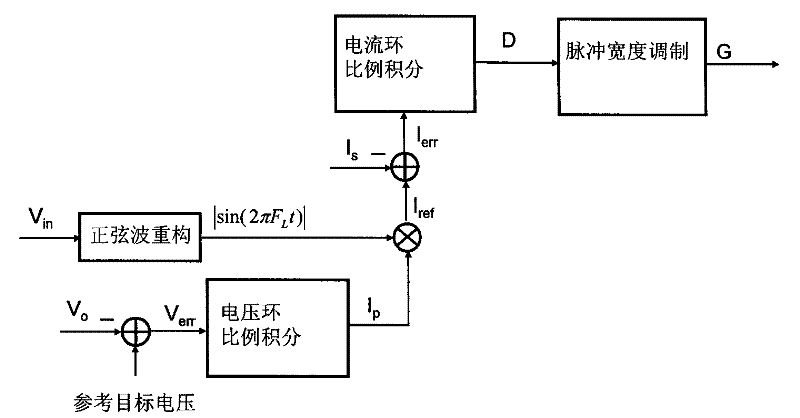
Technical field [0001] The invention relates to a control circuit, in particular to a control circuit for improving power factor correction load response, and belongs to the field of power management. Background technique [0002] The function of the power factor correction circuit is to reduce the interference and impact of the harmonics generated by the electrical appliances on the power grid, thereby reducing the useless power consumption on the power grid. The principle of power factor correction is to adjust the input current waveform to make it consistent with the input voltage waveform; if the input voltage waveform is a sine wave alternating current, the input current waveform must also be a sine wave, and the phases of the two must be consistent. [0003] Such as figure 1 Shown is a feedback control circuit for commonly used power factor correction. Output voltage of rectifier circuit V in Reconstruct the module through sine wave to get the voltage V in |sin(2πF L T)|, ...

Claims


Application Information

Patent Timeline
Patent Type & Authority Patents(China)
IPC IPC(8): H02M7/217H02M1/42
CPCY02B70/126Y02B70/10Y02P80/10
Inventor 林建清
Owner 上海硅虹微电子科技有限公司
Learn More