Axial snubbers for camera

a technology of axial snubbers and cameras, which is applied in the field of cameras, can solve the problems of excessive movement of optics, limited travel of lenses that focus and/or zoom cameras, and so as to reduce the likelihood of undesirable damage, and eliminate the effect of damage typically

Active Publication Date: 2009-06-30
DIGITALPTICS MEMS
View PDF7 Cites 61 Cited by
  • Summary
  • Abstract
  • Description
  • Claims
  • Application Information

AI Technical Summary

Benefits of technology

[0009]According to one embodiment of the present invention, the snubbers limit the motion of optics of a miniature camera that utilize comparatively brittle silicon structures. The snubbers can be formed from a plastic material that is substantially more resilient than silicon. When a structure of the lens assembly contacts the stops of the axial snubbers, contact with the silicon structures is avoided and consequently no damage typically results. That is, use of the axial snubber mitigates undesirable contact with or stress upon the more fragile components and thus reduces the likelihood of undesirable damage thereto.

Problems solved by technology

In this manner, lenses that focus and / or zoom a camera can be limited in travel to the extent necessary for desired functioning of the camera.
Also, excessive movement of the optics, that may cause damage if permitted, can be inhibited.
That is, use of the axial snubber mitigates undesirable contact with or stress upon the more fragile components and thus reduces the likelihood of undesirable damage thereto.

Method used


Image

  • Axial snubbers for camera
  • Axial snubbers for camera
  • Axial snubbers for camera

Examples


Embodiment Construction

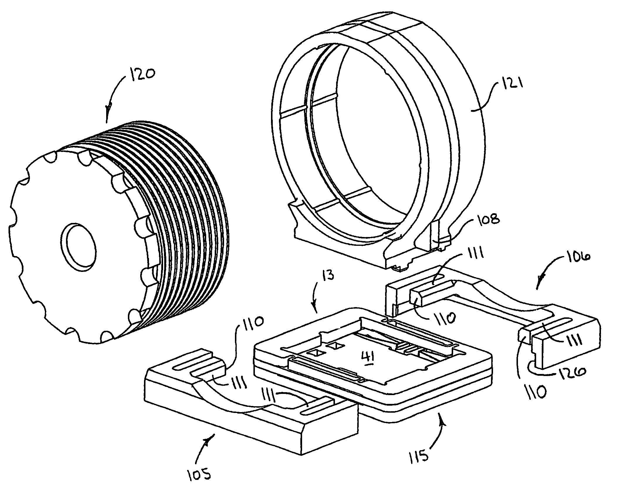
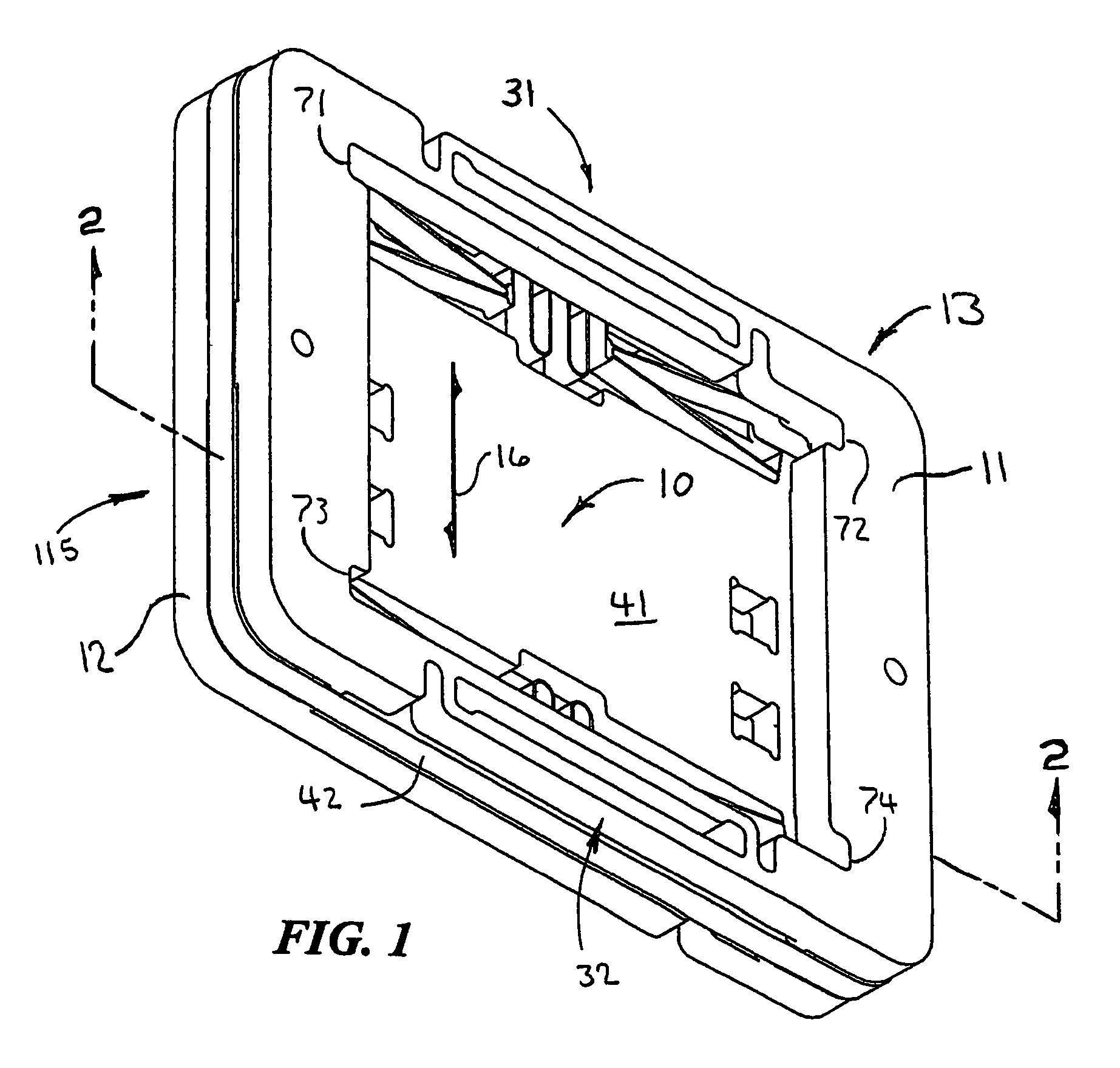
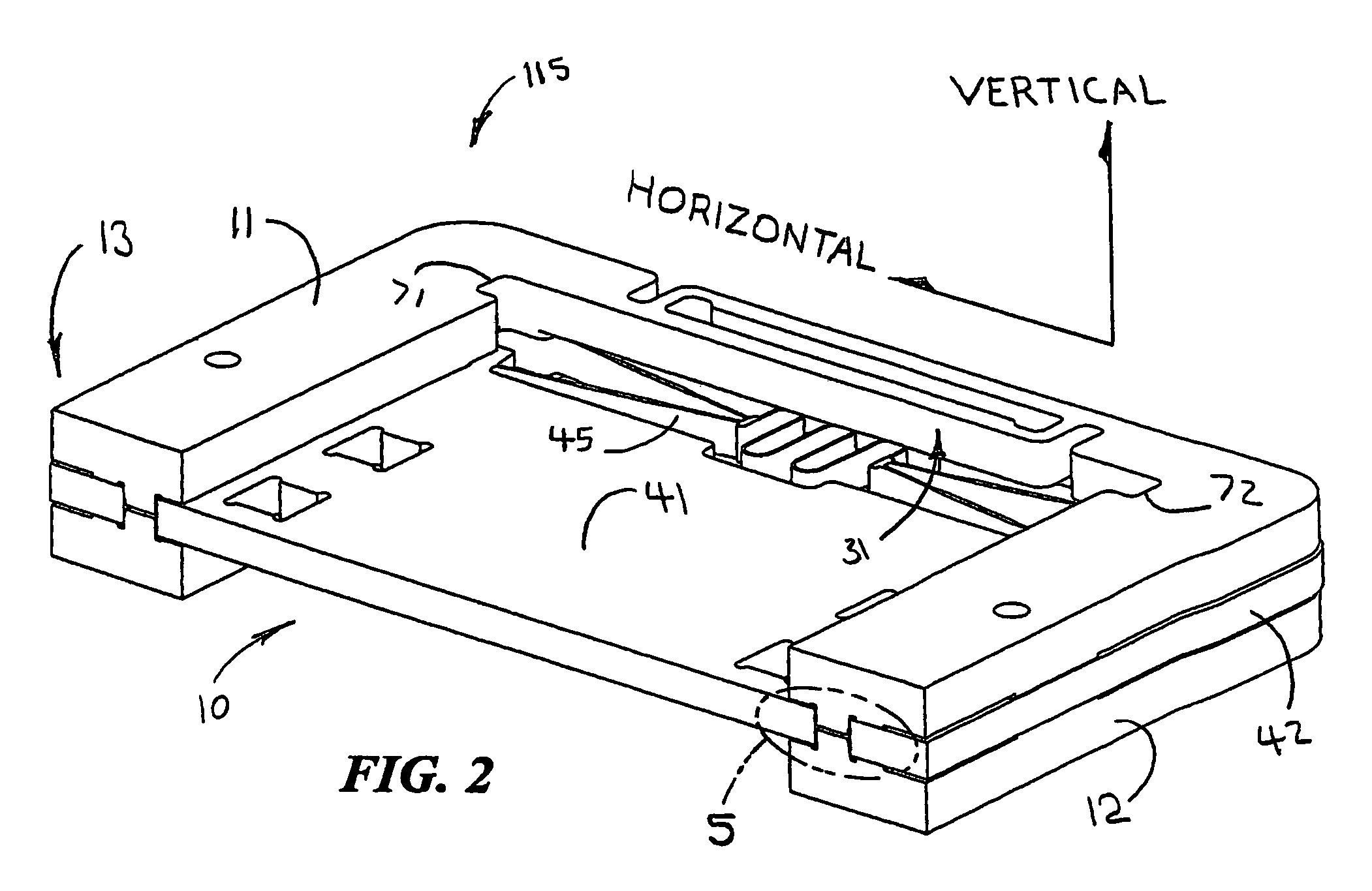
[0023]A method and system for defining the motion of an item is disclosed. For example, according to one embodiment of the present invention, the axial (along the direction of the optical axis) motion of camera optics can be limited. In this manner, axial motion of the camera optics can be restricted to a range that is consistent with desired operation of the camera and which mitigates the likelihood of damage to the camera. For example, one snubber can be configured so as to make one end of the range of focus at infinity and / or another snubber can be configured so as to make the other end of the range of focus the closest focus.

[0024]More particularly, the motion of optics that facilitates focus and / or zoom of a camera can be limited. Such limiting of the motion of camera optics can be particularly beneficial when micro-electromechanical systems (MEMS) components are used to move the camera optics. Such MEMS components can be fragile. For example, such MEMS components can be formed...


PUM


Abstract

A method and system for limiting the motion of items, such as camera optics, are disclosed. A motion limiting member can be used to limit the motion of the item using a surface thereof that abuts a structure of the item. Limits on the motion can be defined by a positioning member that is attached to the motion limiting member and that abuts a structure that is fixed with respect to the desired range of motion of the item whose motion is being limited. This abutment facilitates the precise definition of the limit on the motion of the item.

Description

PRIORITY CLAIM[0001]This patent application claims the benefit of the priority date of U.S. provisional patent application Ser. No. 60 / 657,261, filed on Feb. 28, 2005 and entitled AUTOFOCUS CAMERA pursuant to 35 USC 119. The entire contents of this provisional patent application are hereby expressly incorporated by reference.TECHNICAL FIELD[0002]The present invention relates generally to cameras. The present invention relates more particularly to an axial snubber assembly for limiting the motion of optical elements in a miniature camera, such as a miniature camera that is suitable for use in a cellular telephone.BACKGROUND[0003]Miniature cameras are well known. Miniature cameras are widely used in contemporary cellular telephones. They are also used in other devices, such as laptop computers and personal digital assistants (PDAs). Miniature cameras can even be used as stand alone devices for such applications as security and surveillance.[0004]Contemporary miniature cameras, such as...

Claims


Application Information

Patent Timeline
Patent Type & Authority Patents(United States)
IPC IPC(8): G03B17/00G02B7/02G03B3/00
CPCG03B3/00G03B29/00
Inventor CALVET, ROBERT J.
Owner DIGITALPTICS MEMS
Why Eureka
Try Eureka