Surgical instrument with flexible drive mechanism

a technology of flexible drive mechanism and surgical instruments, which is applied in the direction of surgical forceps, surgical staples, paper/cardboard containers, etc., can solve the problems of not effectively transmitting large amounts of energy, surgical instruments that use high force/low velocity methods often require physically large components, and the physical large components are usually quite rigid, so as to achieve high mechanical advantages

Active Publication Date: 2009-07-07
COVIDIEN LP
View PDF41 Cites 1733 Cited by
  • Summary
  • Abstract
  • Description
  • Claims
  • Application Information

AI Technical Summary

Benefits of technology

[0008]The present application discloses a surgical instrument and a mechanism for use therewith capable of articulating at least 90 degrees with respect to a longitudinal axis defined therealong, and applying the force necessary to operate a surgical tool disposed at a distal end thereof. The mechanism includes a drive member having proximal and distal ends, a crank mechanism operatively connected to the distal end of the drive member, a clutch coupled to the crank mechanism, and a gear rotatable about a central axis and configured to engage a linear driver. The drive member is rotatable and may be flexible. A handle portion attached to the proximal end of the drive member may provide the necessary motion to rotate the drive member. Many types of handle assemblies may be employed to provide rotational motion to the drive member. The rotational motion of the drive member rotates a crank mechanism.
[0011]The linear driver is operatively connected to the gear. The linear driver may be comprised of a rack, a chain or a similar driver. As the gear rotates, the linear driver translates to operate a surgical tool. The instrument hereinabove described has a high mechanical advantage.

Problems solved by technology

Ordinarily, articulating surgical instruments transmit energy along a longitudinal axis of the instrument, and do not effectively transmit large amounts of energy when the end effector is articulated at sharp angles.
Surgical instruments that use high force / low velocity methods often require physically large components.
These physically large components are usually quite rigid and are not easily bent.
The use of such structural elements leads to, among other things, friction and buckling.

Method used


Image

  • Surgical instrument with flexible drive mechanism
  • Surgical instrument with flexible drive mechanism
  • Surgical instrument with flexible drive mechanism

Examples


Embodiment Construction

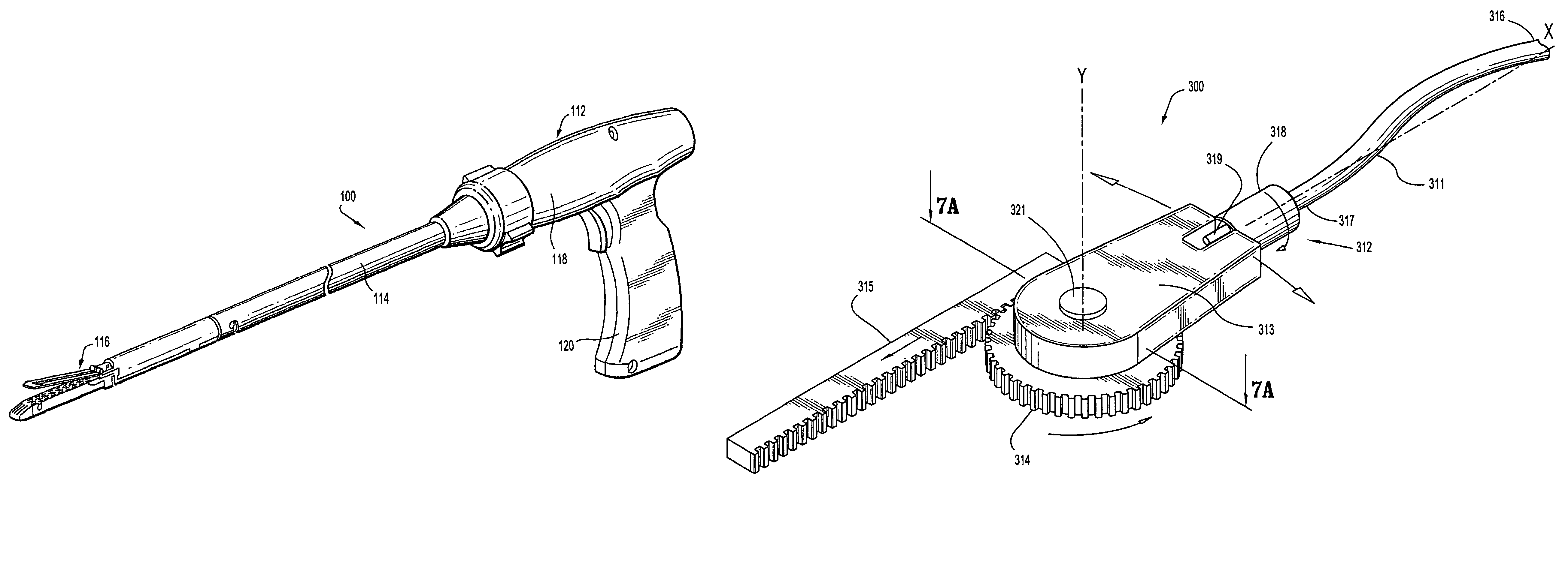
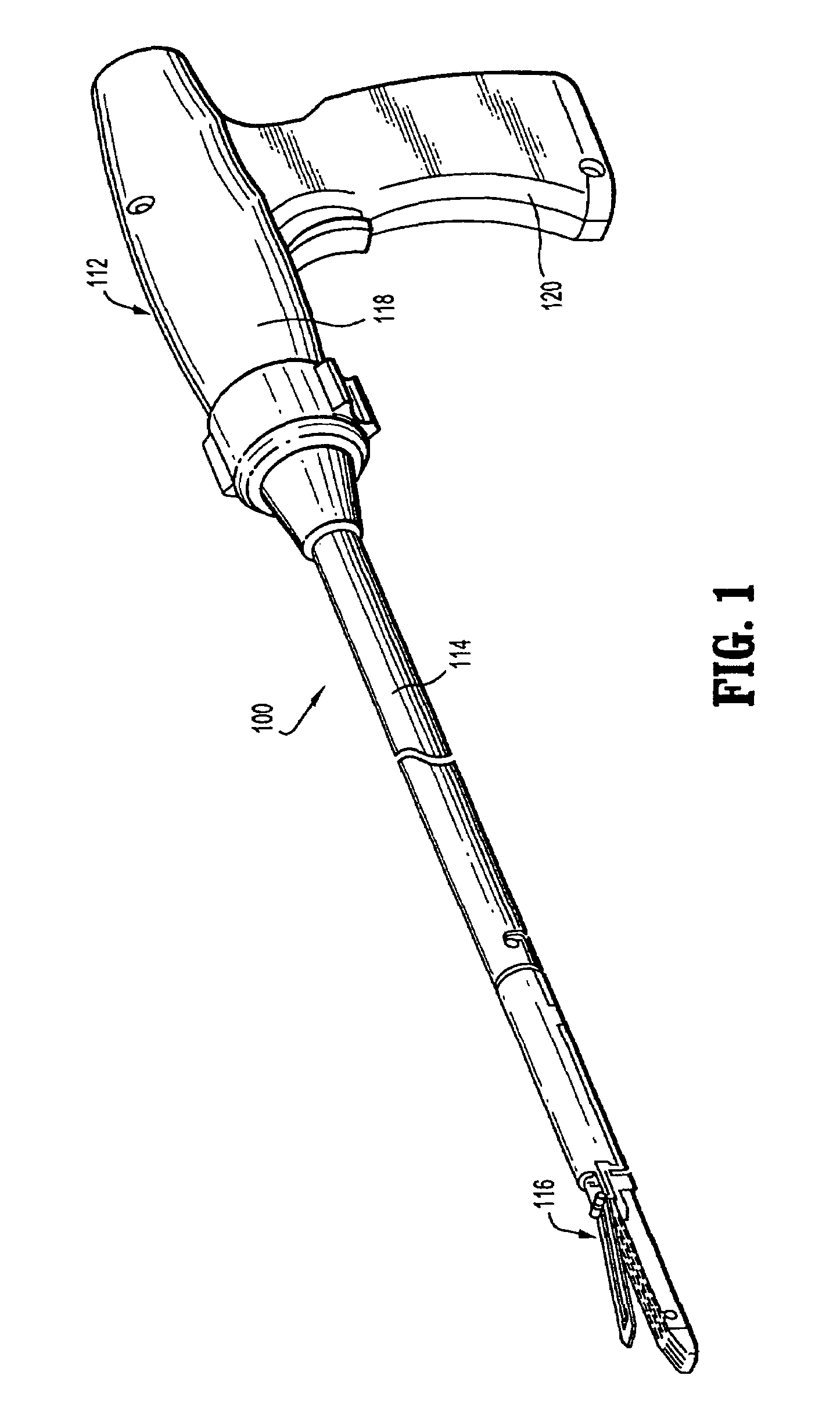
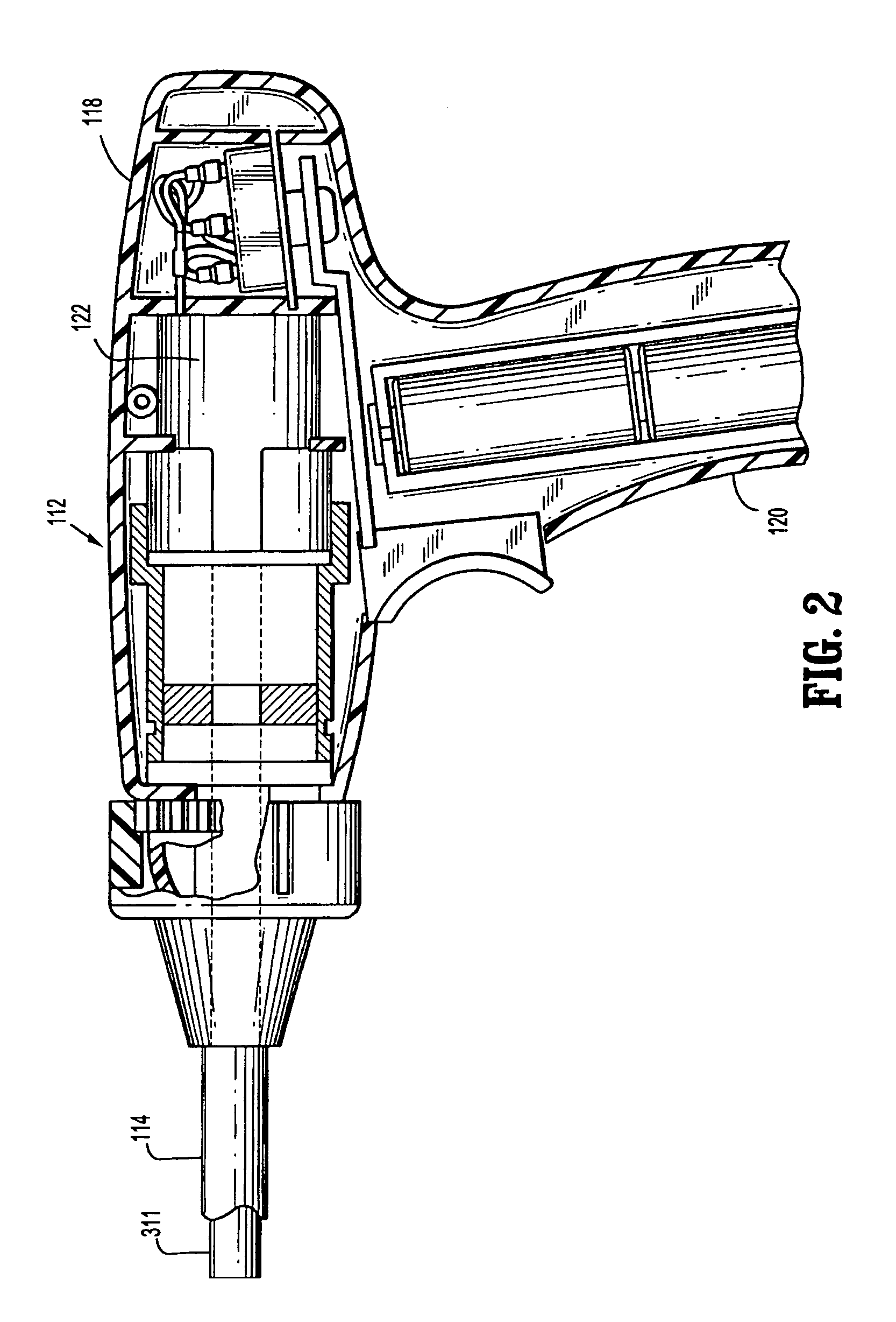
[0034]Embodiments of the presently disclosed surgical instrument and the mechanism for use therewith are now described in detail with reference to the drawings, in which like reference numerals designate identical or corresponding elements in each of the several views. As used herein, the terms “distal” refers to that portion of the surgical instrument, or component thereof, farther from the user while the term “proximal” refers to that portion of the component thereof, closest to the user.

[0035]Referring initially to FIG. 1, a surgical instrument in accordance with an embodiment of the present disclosure is referred to in the figures as reference number 100. Briefly, surgical instrument 100 is configured to clamp body tissue and apply a plurality of surgical fasteners to the body tissue during laparoscopic or endoscopic procedures. In particular, surgical instrument 100 is capable of transmitting the force necessary to operate a surgical tool attached to the distal end thereof at a...


PUM

PropertyMeasurementUnit
bend angleaaaaaaaaaa
anglesaaaaaaaaaa
anglesaaaaaaaaaa

Abstract

A drive mechanism for use with a surgical instrument includes a rotatable drive member, a crank operatively coupled to the drive member; a clutch operatively coupled to the crank, wherein rotational motion of the drive member causes oscillating movement of the clutch; and a gear rotatably coupled to the clutch, wherein the oscillating movement of the clutch causes rotation of the gear. The drive mechanism may further include a gear configured to engage a linear member. The crank may include a pin extending distally therefrom. The clutch may include a slot dimensioned and configured to receive a pin of the crank.

Description

BACKGROUND[0001]1. Technical Field[0002]The present invention relates to surgical instruments and more particularly, to an endoscopic surgical instrument having a flexible drive mechanism.[0003]2. Background of Related Art[0004]Articulating surgical instruments are well-known in the art. Surgeons typically use articulating instruments to reach areas out of line with the entry axis of the surgical instrument. Ordinarily, articulating surgical instruments transmit energy along a longitudinal axis of the instrument, and do not effectively transmit large amounts of energy when the end effector is articulated at sharp angles. Surgical instruments that use high force / low velocity methods often require physically large components. These physically large components are usually quite rigid and are not easily bent.[0005]The operation of current articulating surgical instruments involves the movement of a rod or a long flexible metal strip actuator around a bend. The use of such structural ele...

Claims


Application Information

Patent Timeline
Patent Type & Authority Patents(United States)
IPC IPC(8): A61B17/068
CPCA61B17/07207A61B2017/00398A61B2017/2943A61B2017/2936A61B2017/00407
Inventor VIOLA, FRANK J.
Owner COVIDIEN LP
Why Eureka
Try Eureka