Method of and system for timing training

a timing training and timing technology, applied in the direction of pre-selected time interval producing apparatus, instruments, music, etc., can solve the problems of no device available whose purpose is to measure, compounding the difficulty of determining which of the two sounds occurs first, and difficult to perform dual tasks

Inactive Publication Date: 2009-07-07
ONBOARD RES
View PDF16 Cites 15 Cited by
  • Summary
  • Abstract
  • Description
  • Claims
  • Application Information

AI Technical Summary

Problems solved by technology

These dual tasks are often difficult to perform.
The difficulty of determining which of the two sounds occurs first is compounded when the two sounds are very close together in time.
However, there is no device available whose purpose is to measure and report the relative dynamic level of the user's sounds to the user.

Method used


Image

  • Method of and system for timing training
  • Method of and system for timing training
  • Method of and system for timing training

Examples


Embodiment Construction

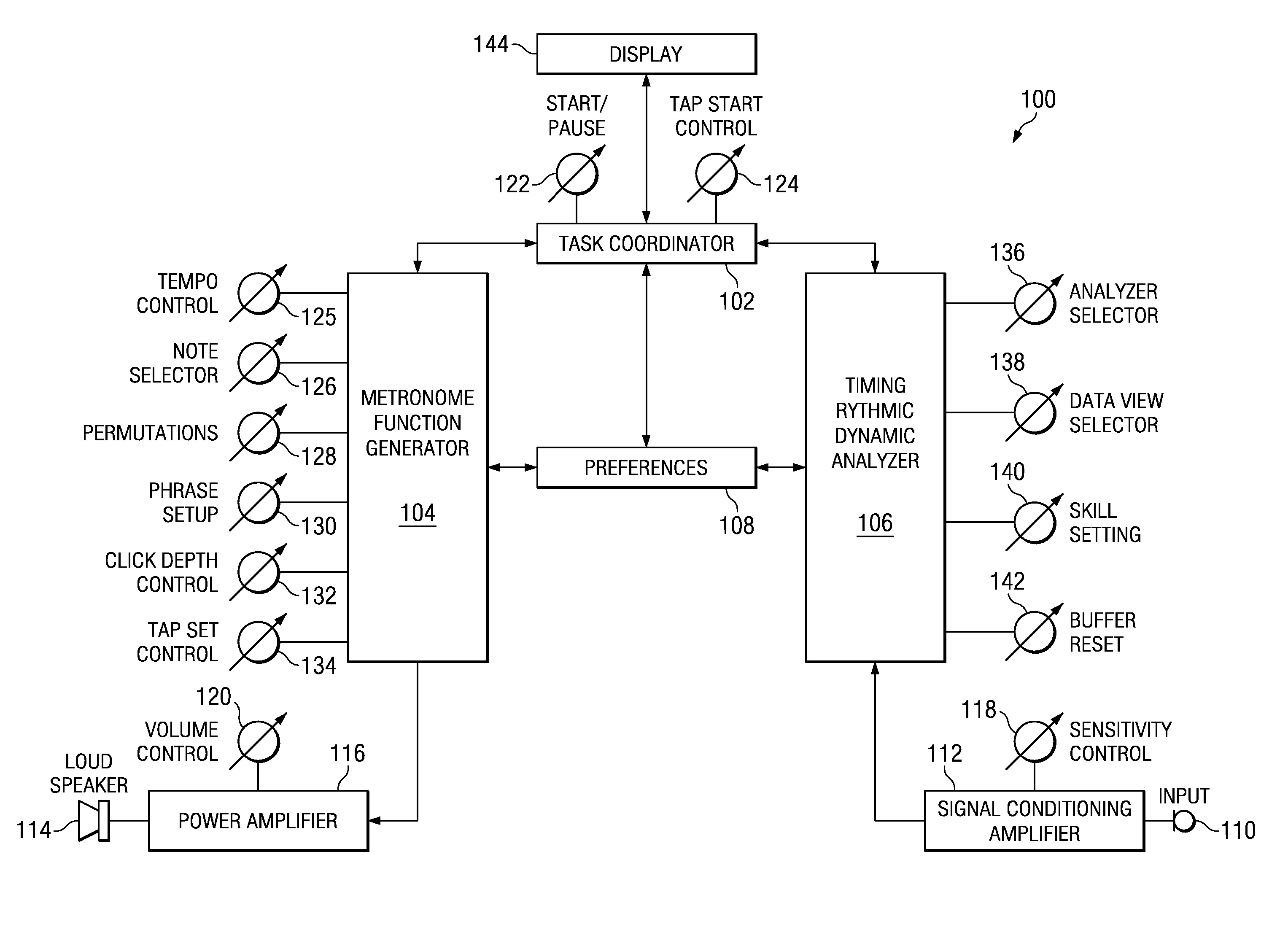
[0027]A system in accordance with principles of the invention enables a user to execute groupings of sounds (e.g., musical notes) and to visually determine changes occurring in dynamic level as well as where in time the sounds occurred relative to each other and relative to an audible reference click sound. The system may be used for purposes of skills improvement and assessment. After setting a desired rhythm, a user may start rhythm playback and begin playing an instrument. The user's notes are detected and a real-time visual representation is created of the timing and dynamic data of sounds generated by the instrument being played.

[0028]In various embodiments of the invention, an electronic device divides a primary metronome beat into multiple time sub-windows. A musical rhythm may be programmed into the electronic device, which generates a series of click sounds and visual indicators (e.g., flashing lights) relating to the programmed rhythm, which visual indicators may be used a...


PUM


Abstract

A timing-training method includes displaying, via a sweep function, a real-time visual indicator responsive to user input and generating a plurality of sounds synchronized with the sweep function.

Description

CROSS-REFERENCE TO RELATED APPLICATIONS[0001]This patent application claims priority from, and incorporates by reference the entire disclosure of, U.S. provisional patent application No. 60 / 730,220, filed on Oct. 25, 2005.BACKGROUND[0002]Placement of musical notes in time relative to one another is a foundational element of music and is typically referred to as timing and rhythm. Executing groupings of notes with accurate relative timing is vital for musicians to be able to start together and end together without speeding up, slowing down, or otherwise getting separated during the course of a performance. Musicians have, for thousands of years, sought ways to improve their timing and rhythmic skills.[0003]In 1812, Dietrik Winkel found that a double-weighted pendulum (i.e., a pendulum having a weight on each side of a pivot) would swing as slowly as 25 swings per minute, even when the pendulum was made of short length. Johann Nepenuk Maelzel appropriated Winkel's idea and, in 1816, s...

Claims


Application Information

Patent Timeline
Patent Type & Authority Patents(United States)
IPC IPC(8): G09B15/00
CPCG04F5/02G04F5/025G09B15/02G09B15/04G10H1/40G10H1/42G10H3/12G10H1/46G10H2220/185G10H2210/076G10H2210/091G10H2220/005G10H2220/081
Inventor WILSON, MARK L.MEMBRENO, AGUSTIN J.NIRUMANDRAD, MOHAMMADREZA
Owner ONBOARD RES
Why Eureka
Try Eureka