
Image forming apparatus and image forming method

a technology of image forming apparatus and forming method, which is applied in the direction of electrographic process apparatus, instruments, optics, etc., can solve the problems of user forgetting to perform the aforementioned setting of paper type, plurality of paper types, image forming apparatus, etc., and achieves the effect of reducing the accuracy of identifying paper type and good imag

Inactive Publication Date: 2009-07-07
CANON KK
View PDF10 Cites 8 Cited by
  • Summary
  • Abstract
  • Description
  • Claims
  • Application Information

AI Technical Summary

Benefits of technology

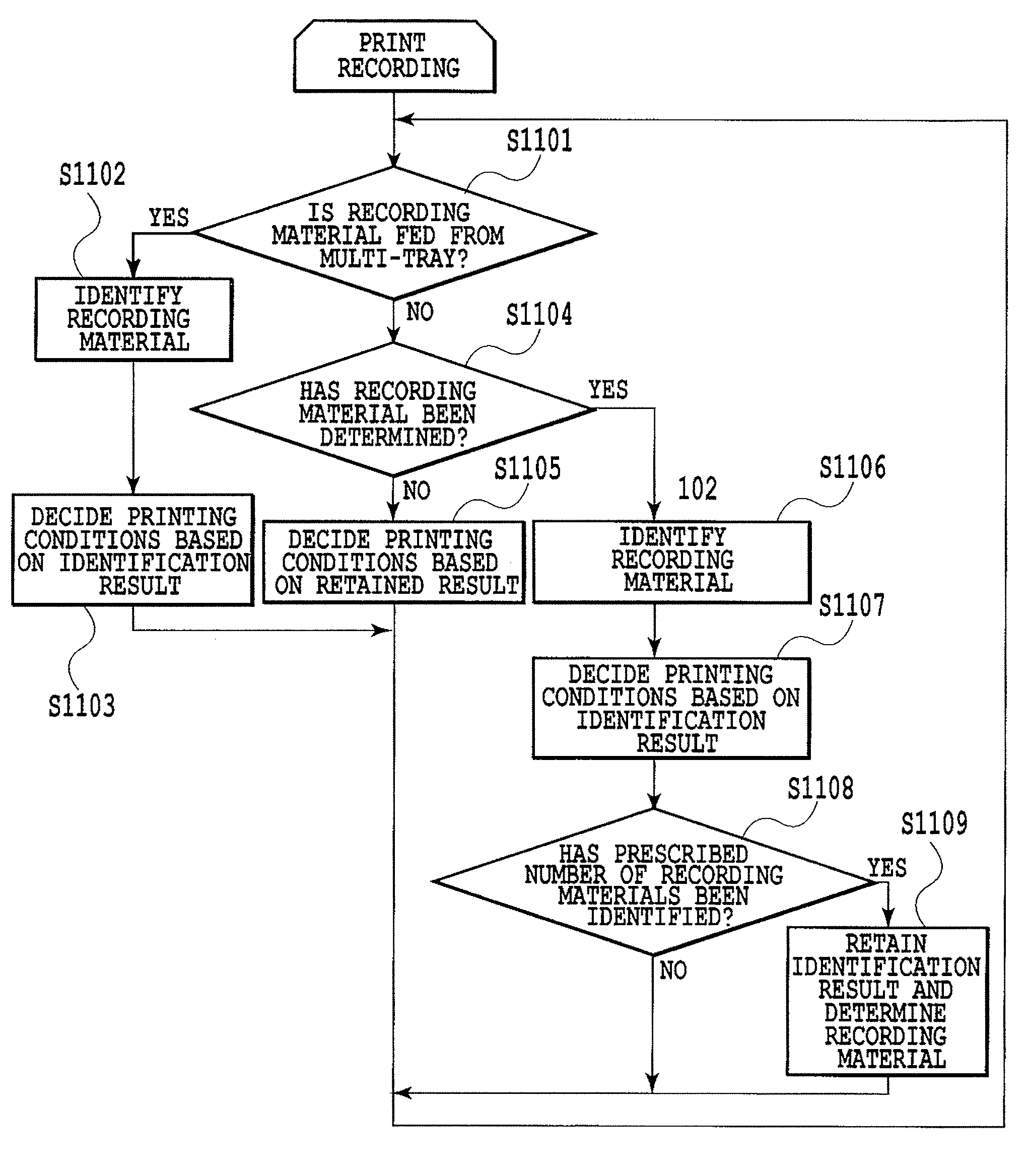
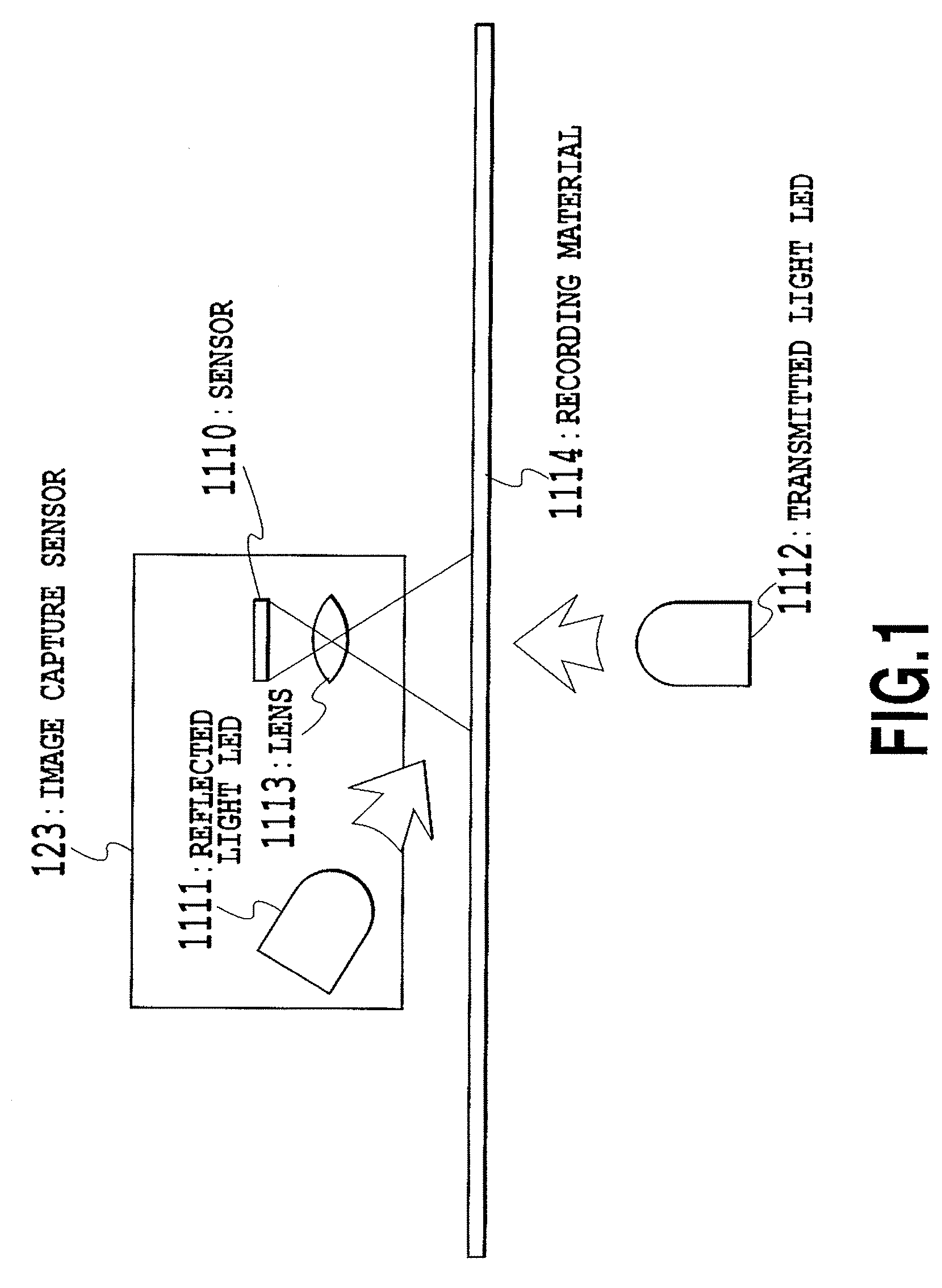
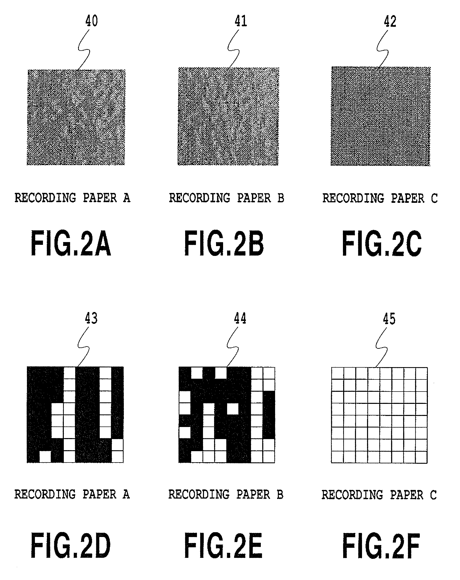
The present invention proposes a configuration to identify sheets of paper with minimal impact on productivity and performance. The invention provides an image forming apparatus and method that can detect the type of paper fed from a paper feed section and control the printing process accordingly. By recording and storing information about the type of paper for each paper feed port, the apparatus can perform printing control suitable for the recording materials while maintaining system performance. Compared to identifying paper for every sheet or printing job, the invention reduces the number of times of paper identification and increases accuracy.

Problems solved by technology

However, the user may forget to perform the aforementioned setting of the paper type, make a mistake in the setting, or mix a plurality of paper types.
However, the aforementioned conventional image forming apparatuses have the following problems.
However, if it is configured that all the recording materials are identified, every identification operation takes time, and the productivity is lowered.
Moreover, in the case where the identification is performed only on the first sheet of each job and the subsequent sheets are processed using the identification result of the first sheet for control as described above, if the identification of the first sheet is wrong, all the subsequent sheets are subjected to control based on the wrong identification result.

Method used


Image

  • Image forming apparatus and image forming method
  • Image forming apparatus and image forming method
  • Image forming apparatus and image forming method

Examples


first embodiment

[0035]The present invention is used in general image forming apparatuses as shown in FIGS. 12 to 14.

[0036]In FIG. 12, an image forming apparatus 101 includes a paper cassette 102; a paper feed roller 103; a transfer belt driving roller 104;a transfer belt 105; photoconductive drums 106 to 109 for yellow, magenta, cyan, and black colors, respectively; transfer rollers 110 to 113 for yellow, magenta, cyan, and black colors, respectively; cartridges 114 to 117 for yellow, magenta, cyan, and black colors, respectively; optical units 118 to 121 for yellow, magenta, cyan, and black colors, respectively; a fixation unit 122; a paper presence sensor 128; and a conveying roller 225 to convey paper. The paper presence sensor 128 senses the presence of paper in the paper cassette 102.

[0037]The image forming apparatus 101 generally uses an electrophotographic process. In this process, yellow, magenta, cyan, and black images are transferred on recording materials P so as to be superimposed on ea...

second embodiment

[0094]The basic configuration of the second embodiment is similar to that of the aforementioned first embodiment, except the method of changing the stored type of the recording material, and detailed description thereof is omitted.

[0095]In this embodiment, it is detected that the recording material inside a paper feed port has changed. When printing a first print job after the change, the recording material identification unit performs an operation to re-identify recording materials inside the paper feed port, and then the printing conditions are set again, or reviewed, based on the indication result thereof. Moreover, the identification result is stored and is utilized when a following print job is printed.

[0096]The change of recording materials inside the paper feed port can be detected by monitoring insertion of the cassette. The cassette is often removed and inserted when recording materials are changed or added. The identification of the recording materials performed after the ...

third embodiment

[0103]This embodiment is a mode obtained in a case where the aforementioned second embodiment is applied to an image forming apparatus including a so-called multi-tray. FIG. 14 shows an image forming apparatus including a multi-tray 300. The recording material P set in the multi-tray 300 is fed by a multi-tray paper feed roller 301 and is led to the convey roller 225. The multi-tray 300 is a tray in which various types (various sizes) of recording materials can be loaded according to user's intended use.

[0104]In an image processing apparatus such as a copier, a printer, and a facsimile, it is required that various types of recording materials can be used. There has been an increasing demand especially for thick paper and special paper such as high glossy paper, label paper, and OHT, among the various types of recording materials. Many image processing apparatuses include a recording material accommodating section called a multi-tray as means for feeding such recording materials. The...


PUM


Abstract

In an image forming apparatus identifying recording materials to decide printing conditions, information concerning the type of the recording materials identified by a recording material identification unit is stored for each paper feed port. In a subsequent print job to be printed, the use of the information having been stored in advance makes it possible to omit the recording material identification process for the subsequent recording materials. This stored information includes individual information for each recording material and a determined value obtained from a plurality of a plurality of pieces of individual information. Once the determined value is set, the determined value is used thereafter. These pieces of stored individual information and the determined value are initialized when a change of paper or the like is detected at the paper feed port corresponding to the value and to the information.

Description

BACKGROUND OF THE INVENTION[0001]1. Field of the Invention[0002]The present invention relates to an image forming apparatus including a detection unit detecting information concerning a recording material on which an image is formed, and relates to an image forming method thereof. More specifically, the present invention relates to an image forming apparatus, such as an ink jet printer, a copier, and a laser printer, which controls image forming conditions based on a result of detection performed by a detection unit detecting information concerning properties or a type of the recording material and perform an image forming operation according to the properties or the type of the recording material, and relates to an image forming method thereof.[0003]2. Description of the Related Art[0004]Image forming apparatuses which form an image based on an image signal are of various types such as an electrophotographic type and an ink jet type. In such an image forming apparatus, printing pap...

Claims


Application Information

Patent Timeline
Patent Type & Authority Patents(United States)
IPC IPC(8): G03G15/00
CPCG03G15/5029
Inventor AOKI, MASARU
Owner CANON KK
Learn More