Pneumatic testing for gas chromatograph inlet

a gas chromatograph and gas chromatograph technology, applied in the field of gas chromatographs, can solve the problems of deformation of the ability to reseal the holes formed by the needle, and prone to leakage of the septum b>16/b>

Active Publication Date: 2009-07-14
AGILENT TECH INC
View PDF6 Cites 5 Cited by
  • Summary
  • Abstract
  • Description
  • Claims
  • Application Information

AI Technical Summary

Problems solved by technology

However, the septum 16 is prone to developing leaks because its ability to reseal the holes formed by the needle degrades over time and repeated use.
Any leakage from the septum 16 is problematic because it may invalidate a GC measurement.
However, septum leaks are random so a replacement schedule only gives a margin of protection.
Furthermore, changing the septum alone will not prevent or cure leaks elsewhere within the GC inlet 11.
Such a leak could be the result of temperature cycling or may happen during column maintenance.
A leak may even be caused by a broken column.
Other flow disruptions that invalidate a GC measurement—such as clogs or other obstructions—may also exist.

Method used


Image

  • Pneumatic testing for gas chromatograph inlet
  • Pneumatic testing for gas chromatograph inlet
  • Pneumatic testing for gas chromatograph inlet

Examples


Embodiment Construction

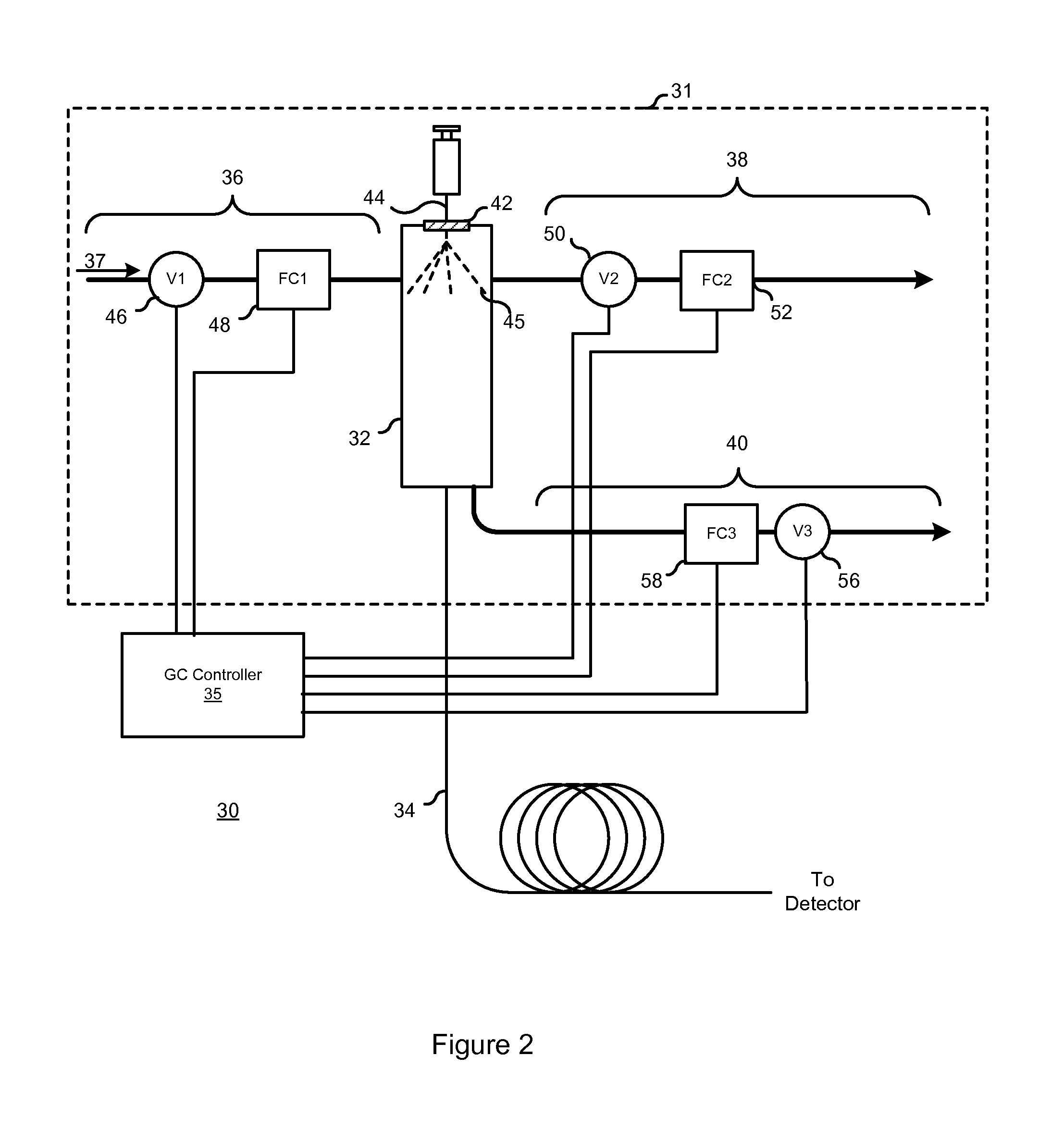
[0015]FIG. 2 shows a schematic diagram of a portion of a gas chromatograph (GC) 30. The GC 30 includes a GC inlet 31 that leads to a column 34, and a GC controller 35 for controlling the GC 30. The GC 30 includes other components that are not shown here, to avoid unnecessarily complicating the figure and the discussion below.

[0016]The GC inlet 31 includes an inlet body 32, an input branch 36 for bringing carrier gas 37 into the inlet body 32, a septum purge branch 38 for exhausting carrier gas 37 from the inlet body 32, and a split vent branch 40 which also exhausts carrier gas 37 from the inlet body 32.

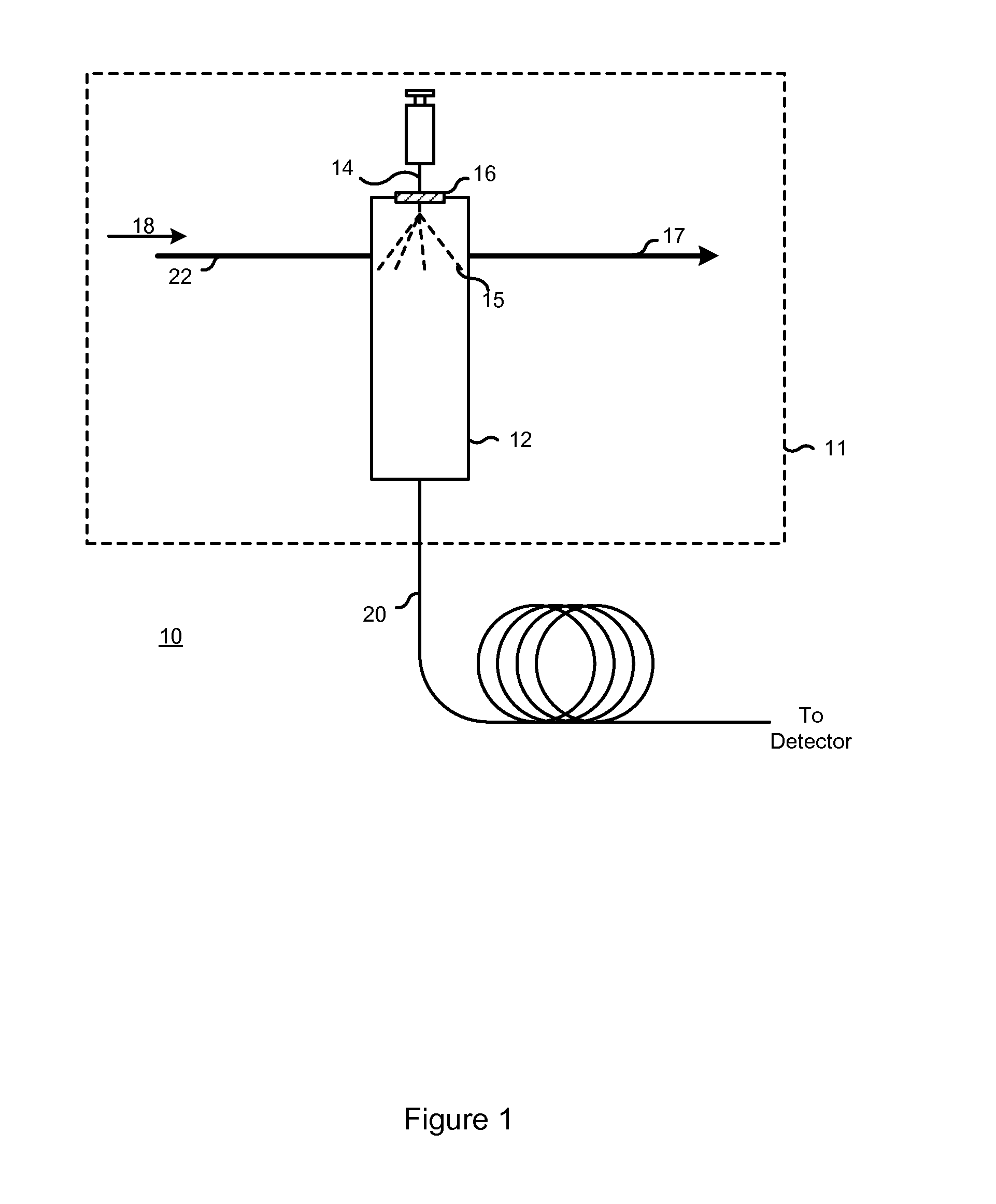
[0017]The inlet body 32 is covered by a septum 42. A needle 44 is inserted through the septum 42 to inject a sample 45 into the inlet body 32. The inlet body 32 vaporizes the sample 45, which is then carried by the carrier gas 37 through the column 34 to a detector (not shown). A portion of the carrier gas 37 flows underneath the septum 42 and out of the inlet body 32 through the sep...


PUM

PropertyMeasurementUnit
pressureaaaaaaaaaa
pressureaaaaaaaaaa
gas chromatographaaaaaaaaaa

Abstract

A method and apparatus for detecting a flow disruption within a gas chromatograph (GC) inlet. A controller controls an input flow of a gas entering a chamber of the GC inlet, and the output flow of gas leaving the chamber. A flow disruption is detected when at least one of the input and output flows deviates from a target value.

Description

BACKGROUND OF THE INVENTION[0001]A gas chromatograph (GC) is an instrument that is used to separate volatile components of a sample. A GC is typically used in combination with a suitable detector (e.g. a mass spectrometer) to analyze, identify, and / or measure individual components within the sample.[0002]FIG. 1 shows a high-level schematic diagram of a portion of an exemplary gas chromatograph (GC) 10. The GC 10 includes a GC inlet 11 connected to a column 20. A carrier gas 18 flows into an inlet body 12 via an input path 22. A liquid sample 15 is introduced into the inlet body 12 by a needle 14. The inlet body 12 is a heated chamber for evaporating the liquid sample 15. The inlet body 12 is covered by a septum 16, which is a flexible material through which the needle 14 is inserted to inject the liquid sample 15. A portion of the carrier gas 18 flows underneath the septum 16 to prevent contamination of the current analysis by material left on the septum by previous injections. This...

Claims


Application Information

Patent Timeline
Patent Type & Authority Patents(United States)
IPC IPC(8): G01N30/04B01D53/02
CPCG01N30/18G01N30/32G01N2030/324G01N2030/185G01N2030/025
Inventor THOMPSON, MICHAEL Q.
Owner AGILENT TECH INC
Why Eureka
Try Eureka