Flow dividing device for a condensation steam turbine having a plurality of outlets

A technology of diverting device and steam turbine, applied in safety devices, non-variable-capacity engines, mechanical equipment, etc., can solve the problems of damage to the thermodynamic efficiency of condensing steam turbines, high flow loss of steam flow, etc., to avoid flow separation, high The effect of thermal efficiency

Inactive Publication Date: 2013-05-01
SIEMENS AG
View PDF6 Cites 0 Cited by
  • Summary
  • Abstract
  • Description
  • Claims
  • Application Information

AI Technical Summary

Problems solved by technology

Risk of flow separation on the suction side, resulting in high flow losses of the steam flow
This flow loss impairs the thermodynamic efficiency of the co

Method used


Image

  • Flow dividing device for a condensation steam turbine having a plurality of outlets
  • Flow dividing device for a condensation steam turbine having a plurality of outlets
  • Flow dividing device for a condensation steam turbine having a plurality of outlets

Examples


Embodiment Construction

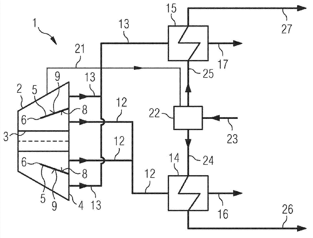
[0017] as from Figures 1 to 5 As can be seen in , the condensing steam turbine 1 has a waste steam casing 2 in which a turbine rotor 3 is arranged. During operation of the condensing steam turbine 1 , the total steam mass flow flows through the waste steam casing 2 , which leaves at the waste steam outlet 4 of the waste steam casing 2 .

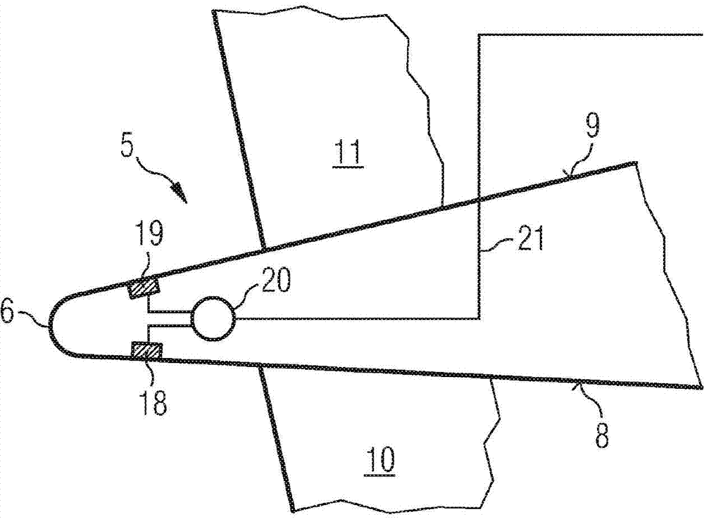
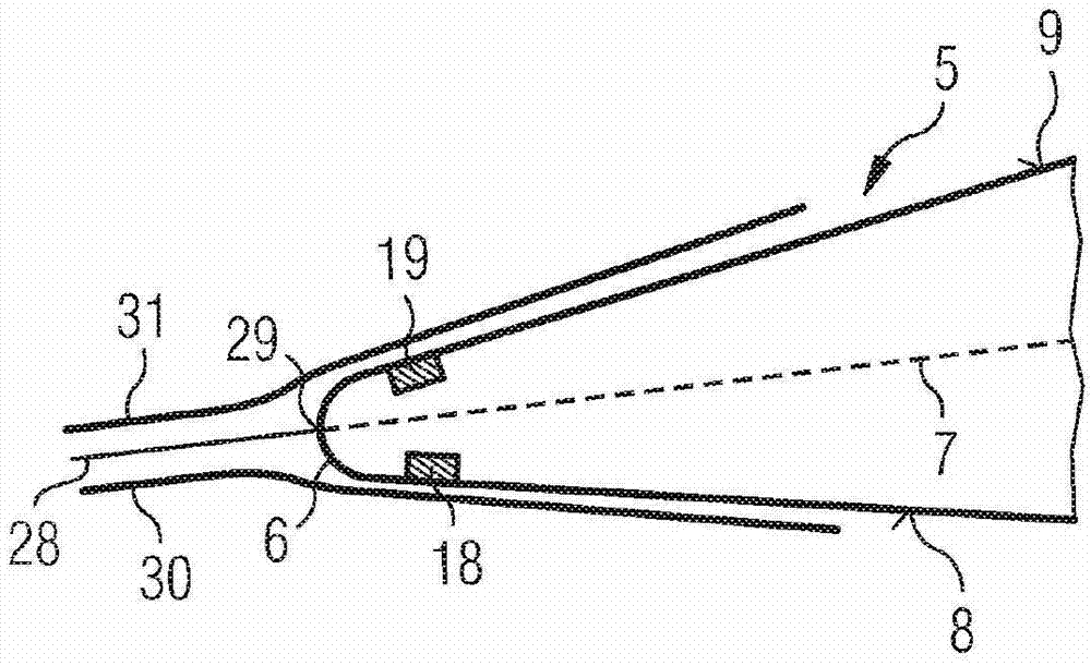
[0018] Arranged in the waste steam casing 2 is a flow divider 5 as an annular web, which is arranged coaxially around the turbine rotor 3 and divides the flow channel in the waste steam casing 2 into an inner region and an outer region. The shunt 5 has a shunt leading edge 6 in which the shunt chord ( ). The inner region of the flow channel of the waste steam casing 2 is delimited by the splitter inner side 8 and the outer region by the splitter outer side 9 , wherein the splitter inner side 8 and the splitter outer side 9 are connected at the splitter leading edge 6 .

[0019] The splitter 5 is held in the exhaust gas casing 2 by inner ...


PUM


Abstract

The invention relates to a flow dividing device for a condensation steam turbine having a plurality of outlets comprising a flow divider (5) dividing the total steam flow within the waste steam housing (2) into two steam flows (30, 31), each flowing through an associated condenser (14, 15), a stagnation point detection device (18-20) for locating the stagnation point (29) formed upon dividing the total steam flow at the front edge of the flow divider (6), and a coolant dividing device (21, 22) by means of which the coolant infeed (23) to the condensers (14, 15) is controlled as a function of the location of the stagnation point (29) such that the stagnation point (29) is centered on the flow divider (5) while avoiding a flow disruption (32).

Description

technical field [0001] The present invention relates to a flow splitter device for a condensing steam turbine having multiple outlets. Background technique [0002] The stage of the condensing steam turbine, which consists of a stationary guide wheel and an impeller rotating about the machine axis, is designed, for example, as a Bowman stage in which annular webs are mounted, by means of which the blade passages are Divided into external and internal subchannels. Here, the steam mass flow in this stage is divided by means of a flow divider into two sub-streams, which are then led to the condenser via a further set of blades via different expansion paths. The web is fitted into the guide vane cascade in a manner crossing the guide vanes, wherein the web has an annular leading edge. [0003] Usually, the webs are rigidly constructed so that the inclination of the leading edge relative to the machine axis of the condensing steam turbine is always constant over time. The infl...

Claims


Application Information

Patent Timeline
IPC IPC(8): F01D21/00F01D17/08F01D1/02F01D25/30
CPCF01D1/023F05D2220/31F01D25/30F01D21/003F01D17/08
Inventor 本杰明·库姆诺贝特·聚尔肯
Owner SIEMENS AG
Why Eureka
Try Eureka