Fuel system having flow-disruption reducer

A fuel system and reducer technology, applied in the direction of charging system, fuel injection pump, fuel injection device, etc., can solve the problem of damage to the filter

Inactive Publication Date: 2015-01-28
CATERPILLAR INC
View PDF5 Cites 0 Cited by
  • Summary
  • Abstract
  • Description
  • Claims
  • Application Information

AI Technical Summary

Problems solved by technology

This pressure spike can cause fuel to flow...

Method used


Image

  • Fuel system having flow-disruption reducer

Examples


Embodiment Construction

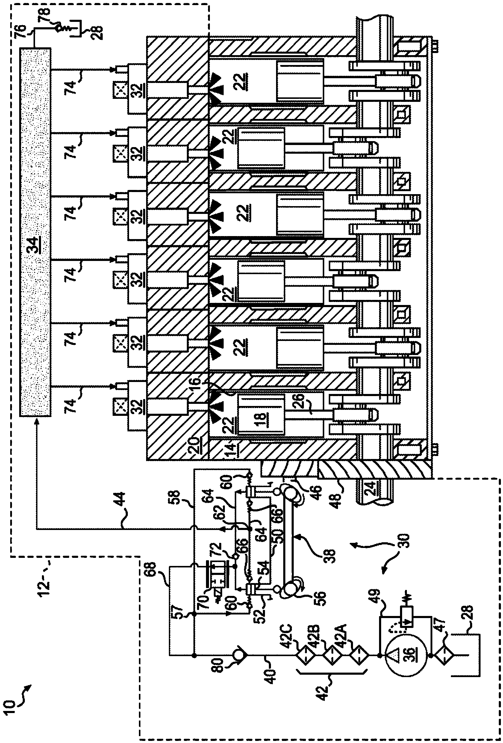
[0011] figure 1 Engine 10 is shown equipped with an exemplary embodiment of fuel system 12 . For the purposes of this disclosure, engine 10 is depicted and described as a four-stroke diesel engine. However, those skilled in the art will recognize that engine 10 may be any other type of internal combustion engine (eg, a gasoline engine). Engine 10 may include an engine block 14 at least partially defining a plurality of cylinders 16 , a piston 18 slidably disposed within each cylinder 16 , and a cylinder head 20 associated with each cylinder 16 .

[0012] Together, cylinder 16 , piston 18 and cylinder head 20 may form combustion chamber 22 . In the illustrated embodiment, engine 10 includes six combustion chambers 22 . However, it is contemplated that engine 10 may include a greater or lesser number of combustion chambers 22, and that combustion chambers 22 may be arranged in an "inline" configuration, a "V" configuration, an opposed-piston configuration, or another suitable...


PUM


Abstract

A fuel system for an engine is disclosed. The fuel system may have a filter, a pump, and a conduit fluidly connected between the filter and the pump. The fuel system may also have a manifold, and a valve movable to direct a first portion of a fuel flow discharged from the pump into the manifold and a remaining second portion of the fuel flow discharged from the pump into the conduit. The fuel system may additionally have a flow-disruption reducer disposed within the conduit between the filter and a discharge location of the remaining second portion of the fuel flow.

Description

technical field [0001] The present disclosure relates to a fuel system, and more particularly, to a fuel system having a flow-disturbance reducer. Background technique [0002] Common rail fuel systems provide a means of simultaneously introducing high-pressure fuel from a common high-pressure supply source to multiple parallel combustion chambers of an engine. A typical common rail fuel system includes a low pressure transfer pump that draws fuel from a fuel tank and supplies fuel to a high pressure pump through one or more filters. The high pressure pump increases the fuel pressure up to eg about 100-300 MPa before introducing the high pressure fuel to the common rail or manifold. The common rail then distributes the fuel to the various injectors in the engine. [0003] One well known type of high pressure pump for supplying fuel to the common rail is the fixed displacement variable delivery pump. Pumps of this type generally include one or more plungers disposed in res...

Claims


Application Information

Patent Timeline
IPC IPC(8): F02M63/02F02M37/00F02M59/46
CPCF02M59/366F02M37/0023F02M63/0245Y10T137/7837Y10T137/794
Inventor C·J·萨尔瓦多P·W·小萨维奇M·T·阿洛特J·R·里斯K·C·亚当斯
Owner CATERPILLAR INC
Why Eureka
Try Eureka