Using counter-bore and capillary geometry to control mesophase pitch-based carbon fiber filament micro and macro structure

a carbon fiber filament and micro-macro technology, applied in the field of counterbore and capillary geometry, can solve the problems of increasing thermal and electrical conductivity, reducing tensile strength, and unsatisfactory for many applications

Inactive Publication Date: 2002-11-07
CONOCO INC
View PDF0 Cites 0 Cited by
  • Summary
  • Abstract
  • Description
  • Claims
  • Application Information

AI Technical Summary

Problems solved by technology

Spinning of high quality fibers from mesophase pitches presents a number of unique problems.
These fibers frequently develop longitudinal cracks rendering them undesirable for many applications.
In general, these fibers have increased thermal and electrical conductivity and reduced tensile strength, and generally poor overall mechanical quality.
This short "spin-draw zone" influences the diameter of the capillaries required to spin small diameter fibers and increases the difficulty of accurate machining of the spinning die.
Small capillary diameters also decrease the length of the time period for continuous spinning before individual capillaries become "slow" or "plugged" and require cleaning and also make cleaning the spinning die more difficult.
As disclosed by Assignee's U.S. Pat. No. 5,259,947, solvated mesophase pitch provides significant advantages over traditional mesophase pitch, however, the unique characteristics of solvated pitch presents novel problems during the spinning of the fibers.
Use of a disruption medium decreases the continuous spinning time possible and increases maintenance time and cost since replacement of the disruption medium may be difficult and time-consuming.
Use of a disruption medium may also result in an undesirable pressure drop across the medium.
Furthermore, placement of the disruption medium adjacent to the entrance of the capillary may result in increase in the incidence of "slow" or plugged capillaries.
Altering the geometry of the capillary or changing the relationship of the capillary to the central cavity increases the difficulty of accurate machining and increases the difficulty of cleaning the die.
Furthermore, use of a capillary having an outlet cross-sectional area greater than the cross-sectional area of the narrowest part of the capillary is ineffective for spinning solvated mesophase pitches because the low viscosity of the pitch and pressure drop at the capillary outlet result in buildup of pitch at the outlet.

Method used


Image

  • Using counter-bore and capillary geometry to control mesophase pitch-based carbon fiber filament micro and macro structure
  • Using counter-bore and capillary geometry to control mesophase pitch-based carbon fiber filament micro and macro structure
  • Using counter-bore and capillary geometry to control mesophase pitch-based carbon fiber filament micro and macro structure

Examples


Embodiment Construction

[0063] The embodiments discussed herein are merely illustrative of specific manners in which to make and use the invention and are not to be interpreted as limiting the scope of the instant invention.

[0064] While the invention has been described with a certain degree of particularity, it is to be noted that many modifications may be made in the details of the invention's construction and the arrangement of its components without departing from the spirit and scope of this disclosure. It is understood that the invention is not limited to the embodiments set forth herein for purposes of exemplification. Like numbers in the drawings indicate like parts in various embodiments of the invention.

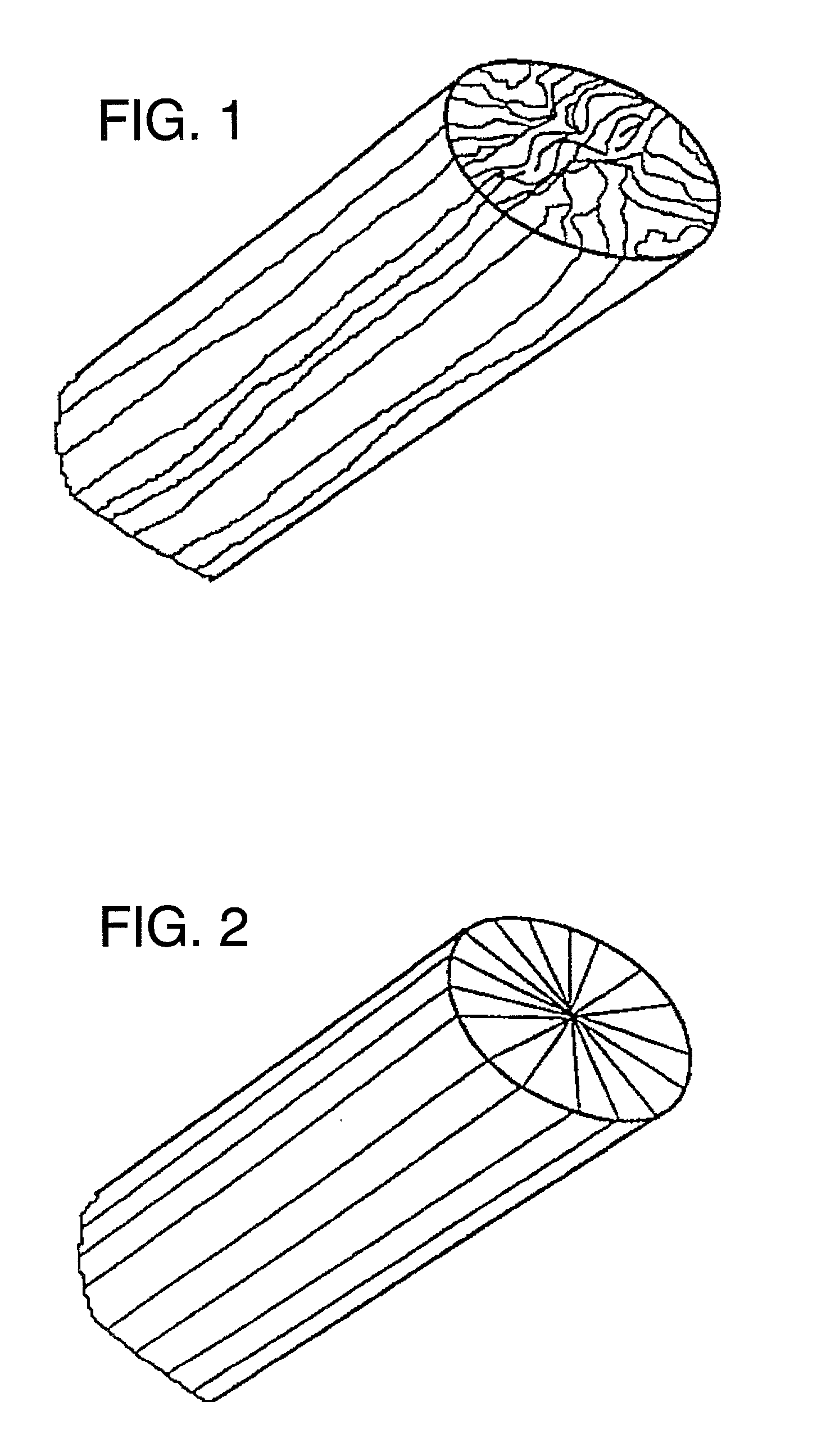
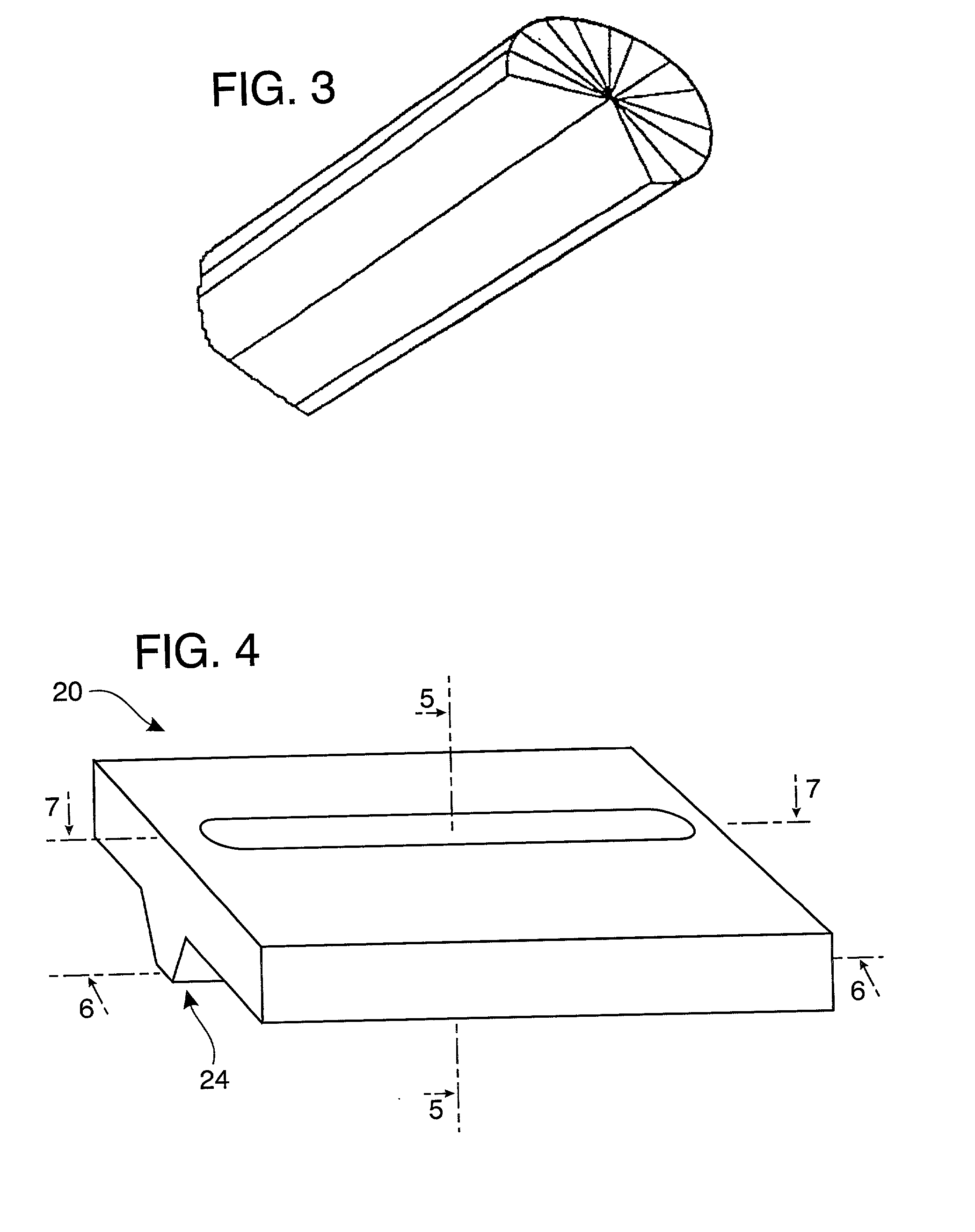
[0065] FIG. 1 illustrates a fiber produced according to the present invention having a non-radial cross-section while FIGS. 2 and 3 illustrate fibers of the prior art.

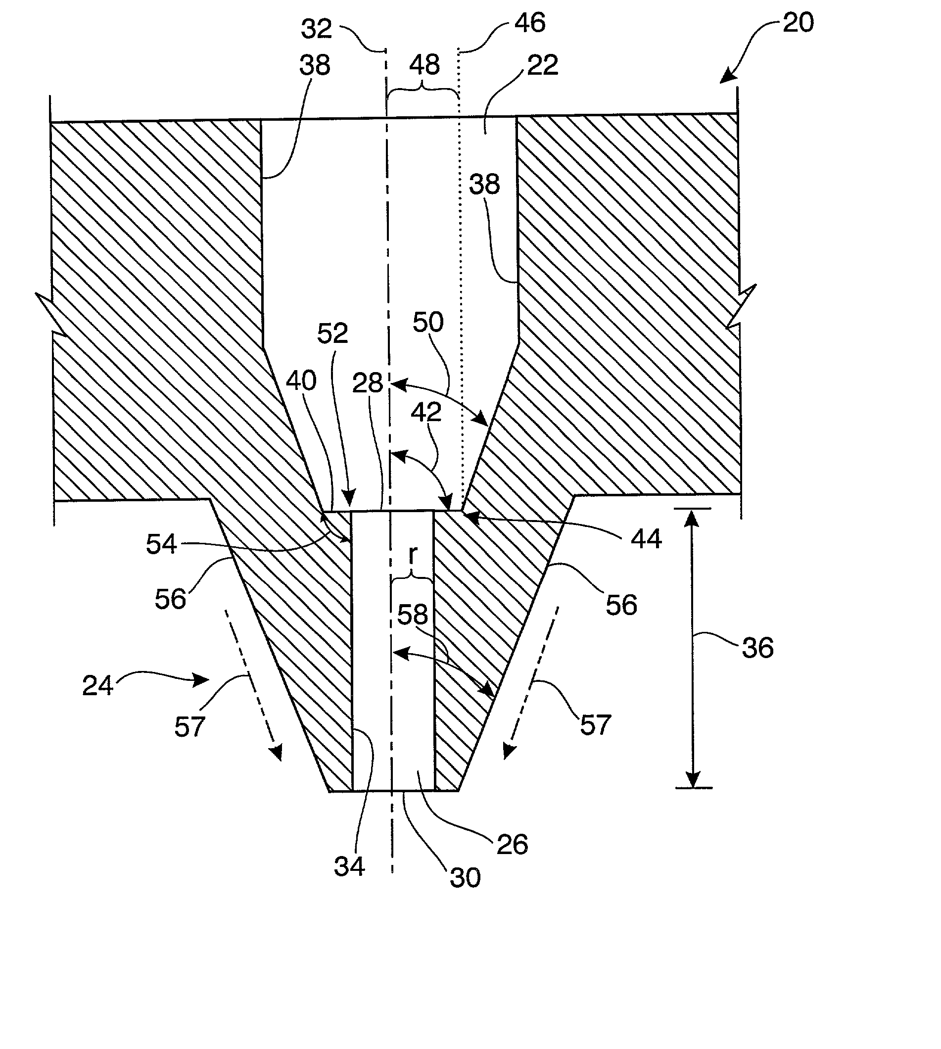
[0066] Referring to FIG. 4, the preferred embodiment of the present invention is a blow spinning die 20 which has a central cavity 2...


PUM

PropertyMeasurementUnit
angleaaaaaaaaaa
angleaaaaaaaaaa
angleaaaaaaaaaa

Abstract

A spinning die for spinning mesophase pitch into carbon fibers. The die includes a central cavity having a bottom and at least one side wall which intersects the bottom. At least one capillary for forming a fiber is in fluid communication with the cavity, the capillary having a first open end, a second open end, an axis and a diameter (d). A flow disruption shoulder is positioned at the juncture of the bottom of the central cavity and the first open end of the capillary to create turbulence at the capillary entrance.

Description

[0001] 1. Field of the Invention[0002] The present invention is directed to a process and apparatus for spinning fibers from mesophase pitches. In particular, the present invention is directed to counter-bore and capillary geometry which will create turbulence at the capillary entrance. The fibers generated according to the present invention have a non-radial cross-section and are predominantly free of longitudinal and helical cracking.[0003] 2. Prior Art[0004] The general methods and devices for melt and blow spinning fibers are well-known. Typically, in melt spinning, a spinnable substance is heated to a temperature which will allow it to flow. This substance then passes, usually under pressure, into a "spinning pack." The spinning pack usually comprises a distribution plate and one or more spinning dies. A typical die will have a central cavity for receiving the spinnable substance and one or more capillaries or needles. The substance is distributed by the distribution plate to t...

Claims


Application Information

Patent Timeline
Patent Type & Authority Applications(United States)
IPC IPC(8): D01D4/02D01F9/145
CPCD01F9/145D01D4/025
Inventor RODGERS, JOHN A.ROSS, ROGER A.ROSSILLON, DANIEL F.
Owner CONOCO INC
Why Eureka
Try Eureka