Combustor mixing joint with flow disruption surface

a technology of mixing joint and flow disruption, which is applied in the direction of machines/engines, stators, lighting and heating apparatus, etc., can solve the problems of increasing mixing losses downstream and mixing losses, and achieve the effect of limiting pressure losses

Active Publication Date: 2018-07-24
GE INFRASTRUCTURE TECH INT LLC
View PDF30 Cites 0 Cited by
  • Summary
  • Abstract
  • Description
  • Claims
  • Application Information

AI Technical Summary

Benefits of technology

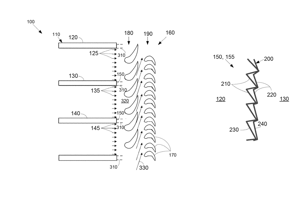
[0007]The present application and the resultant patent further provide a method of limiting pressure losses in a gas turbine engine. The method may include the steps of positioning a mixing joint with a flow disruption surface on a number of can combustors, generating a number of combustion streams in the can combustors, substantially mixing the combustion streams in a low velocity region downstream of the can combustors, and passing a mixed stream to a turbine.

Problems solved by technology

This acceleration may exaggerate the non-uniformities in the flow fields and hence create more mixing losses downstream thereof.
As the now strongly nonuniform flow field enters the stage one bucket, the majority of mixing losses may take place therein as the wakes from the can combustor joints may be mixed by an unsteady flow process.

Method used


Image

  • Combustor mixing joint with flow disruption surface
  • Combustor mixing joint with flow disruption surface
  • Combustor mixing joint with flow disruption surface

Examples


Embodiment Construction

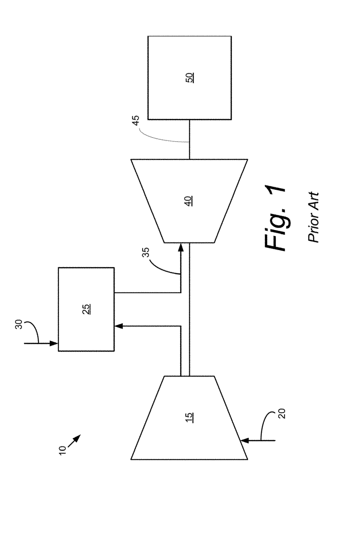
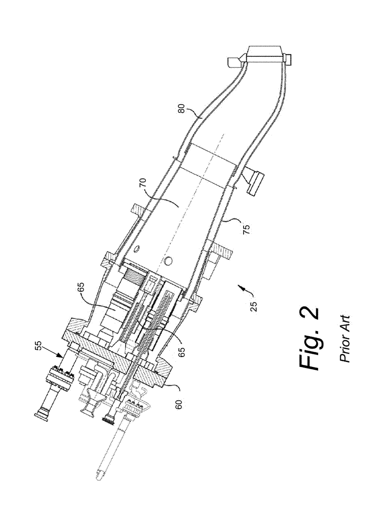
[0018]Referring now to the drawings, in which like numerals refer to like elements throughout the several views, FIG. 1 shows a schematic view of gas turbine engine 10 as may be used herein. The gas turbine engine 10 may include a compressor 15. The compressor 15 compresses an incoming flow of air 20. The compressor delivers the compressed flow of air 20 to a combustor 25. The combustor 25 mixes the compressed flow of air 20 with a compressed flow of fuel 30 and ignites the mixture to create a flow of combustion gases 35. Although only a single combustor 25 is shown, the gas turbine engine 10 may include any number of combustors 25. In this example, the combustor 25 may be in the form of a number of can combustors as will be described in more detail below. The flow of combustion gases 35 is in turn delivered to a downstream turbine 40. The flow of combustion gases 35 drives the turbine 40 so as to produce mechanical work. The mechanical work produced in the turbine 40 drives the com...


PUM


Abstract

A mixing joint for adjacent can combustors may include a first can combustor with a first combustion flow and a first wall, a second can combustor with a second combustion flow and a second wall, and a flow disruption surface positioned about the first wall and the second wall to promote mixing of the first combustion flow and the second combustion flow.

Description

TECHNICAL FIELD[0001]The present application relates generally to gas turbine engines and more particularly relates to a joint between adjacent annular can combustors to promote mixing of the respective combustion streams downstream thereof before entry into the first stage of the turbine.BACKGROUND OF THE INVENTION[0002]Annular combustors often are used with gas turbine engines. Generally described, an annular combustor may have a number of individual can combustors that are circumferentially spaced between a compressor and a turbine. Each can combustor separately generates combustion gases that are directed downstream towards the first stage of the turbine.[0003]The mixing of these separate combustion streams is largely a function of the free stream Mach number at which the mixing is taking place as well as the differences in momentum and energy between the combustion streams. Moreover, a stagnant flow region or wake in a low flow velocity region may exist downstream of a joint be...

Claims


Application Information

Patent Timeline
Patent Type & Authority Patents(United States)
IPC IPC(8): F23R3/46F01D9/02F01D11/00
CPCF23R3/46F01D11/005F01D9/023
Inventor SIDEN, GUNNAR LEIFINGRAM, CLINT L.
Owner GE INFRASTRUCTURE TECH INT LLC
Why Eureka
Try Eureka