Pressure transmission assembly for mounting to a robotic device having a rotatable end effector

Inactive Publication Date: 2009-07-14
WESTERN DIGITAL TECH INC
View PDF7 Cites 45 Cited by
  • Summary
  • Abstract
  • Description
  • Claims
  • Application Information

AI Technical Summary

Problems solved by technology

Unfortunately, for robots having end effectors mounted to a rotatable wrist that require a pressure supply (e.g. pneumatic or hydraulic), the pressure supply source is generally located a relatively long distance away from the end effector.
However, the service tube loops are subjected to a great number of bendings in various directions and with different radii of

Method used


Image

  • Pressure transmission assembly for mounting to a robotic device having a rotatable end effector
  • Pressure transmission assembly for mounting to a robotic device having a rotatable end effector
  • Pressure transmission assembly for mounting to a robotic device having a rotatable end effector

Examples


Embodiment Construction

[0021]In the following description, numerous specific details are set forth. However, it is understood that embodiments of the invention may be practiced without these specific details. In other instances, well-known circuits, structures, and techniques have not been shown in order not to obscure the understanding of this description.

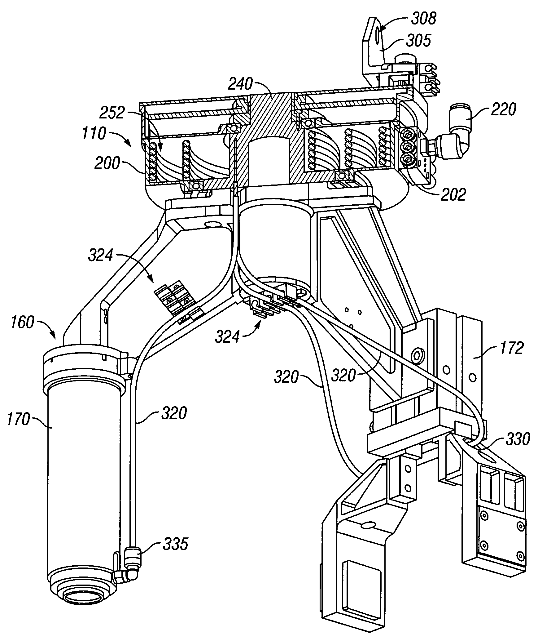
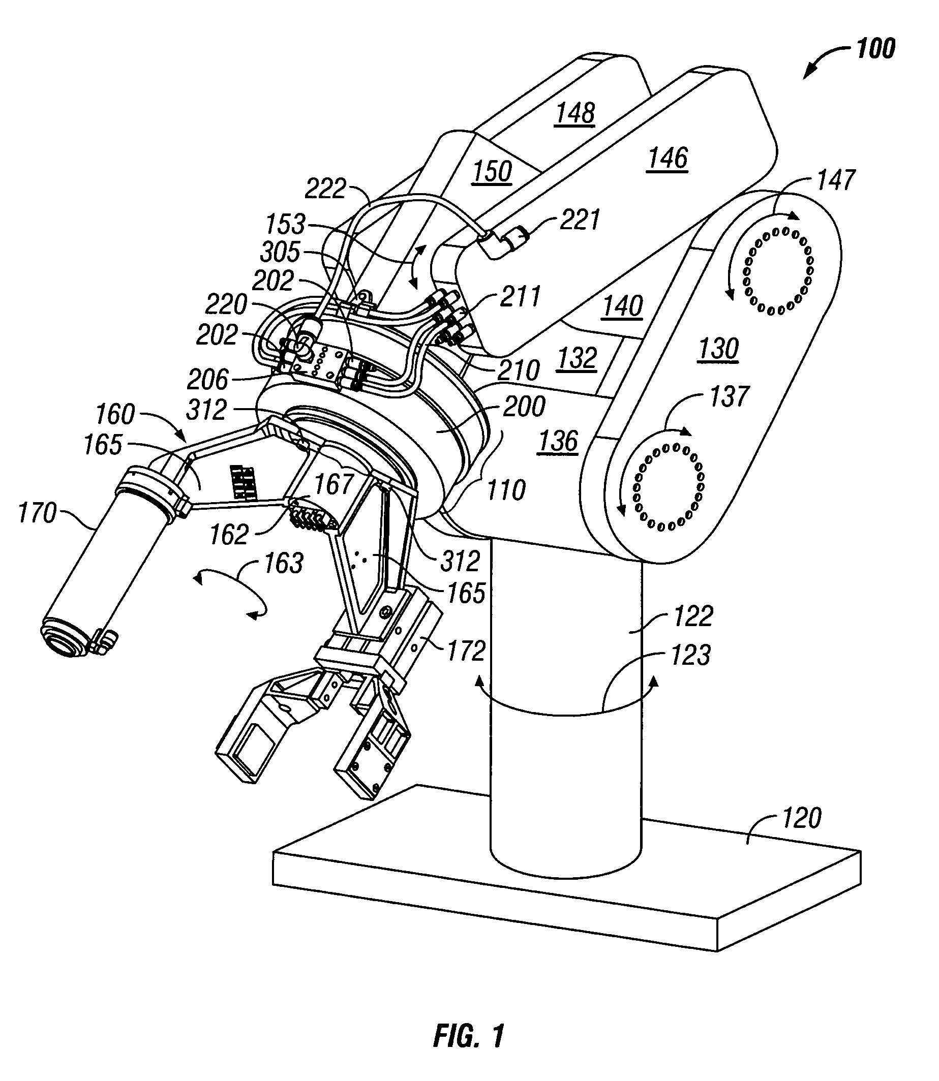
[0022]With reference to FIG. 1, FIG. 1 is a perspective view of a robotic device 100 that may be utilized with embodiments of the invention. As will be described in more detail later, a pressure transmission assembly 110 may be mounted to the robotic device 100.

[0023]As shown in FIG. 1, robotic device 100 may be mounted to a base 120 by a rotatable shaft 122 that rotates through a range of motion indicated by line 123 about the axis of shaft 122. A pair of opposed first arm portions 130 and 132 may be mounted to rotatable shoulder 136 and rotatable elbow 140. Rotatable shoulder 136 is mounted to rotatable shaft 123. Rotatable shoulder 136 rotates first ...


PUM


Abstract

Disclosed is a pressure transmission assembly for mounting to a robotic device having a rotatable end effector. The pressure transmission assembly includes a housing and a flexible pressure transmission member. The housing includes an input port and an output port. The flexible transmission member is coupled between the input port and the output port of the housing. The flexible transmission member is wound within the housing between the input port and the output port and is configured to receive a pressure signal at the input port and to transmit the pressure signal to the end effector through the output port.

Description

BACKGROUND[0001]1. Field of the Invention[0002]The present invention relates to robotic devices. More particularly, the present invention relates to a pressure transmission assembly for mounting to a robotic device having a rotatable end effector.[0003]2. Description of the Prior Art and Related Information[0004]Robotic devices having jointed-arms may be utilized to perform complex actions by the various sections of the robot arm pivoting and rotating around various joints or axes. Further, a wrist is typically attached to the robot arm. The wrist may often pivot or rotate along two axes.[0005]Attached to the wrist may be one or more end effectors that need to be supplied with energy, pressure, medium, coolant, etc., to perform their various functions. This supply may take place via a plurality of connections, which may be formed as electric cables, hoses, pressure tubes, or the like. The end effectors typically require the supply during all the movements of the end effector for lon...

Claims


Application Information

Patent Timeline
IPC IPC(8): B25J15/06B25J15/08B25J17/02
CPCB25J19/0041B25J19/0025
Inventor JONES, NATHAN R.
Owner WESTERN DIGITAL TECH INC
Why Eureka
Try Eureka